
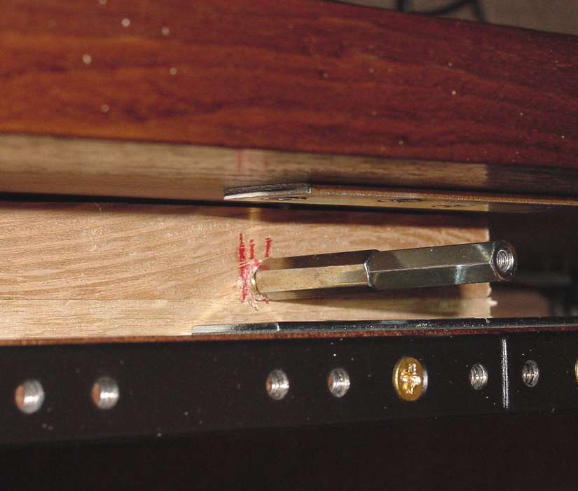
Drilling holes on the inside for power supply PCB. I had to use one of those flexible shafts to get inside.
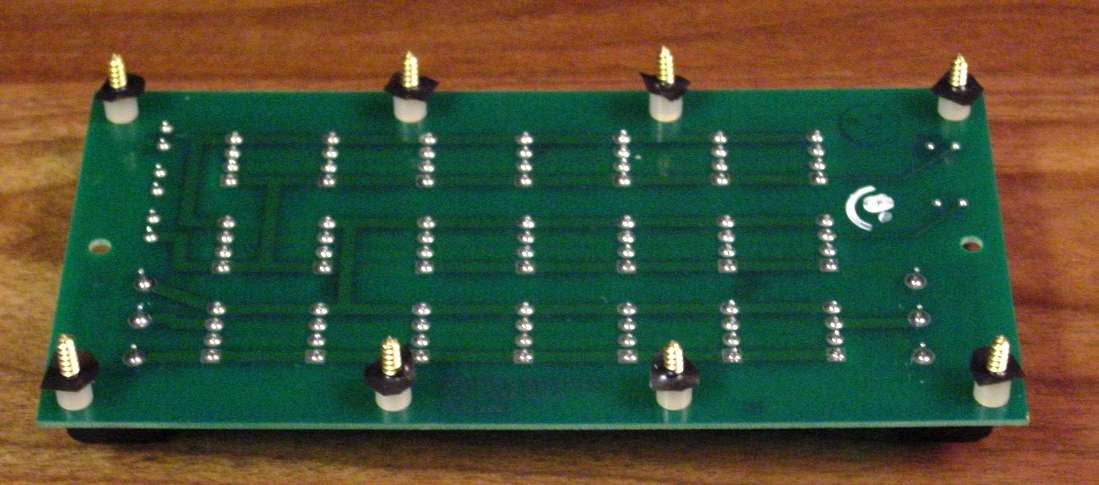
Add spacers to bottom of PCB. I used nylon ¼". The black tape holds them in place until the PCB is screwed in place. Otherwise…. J
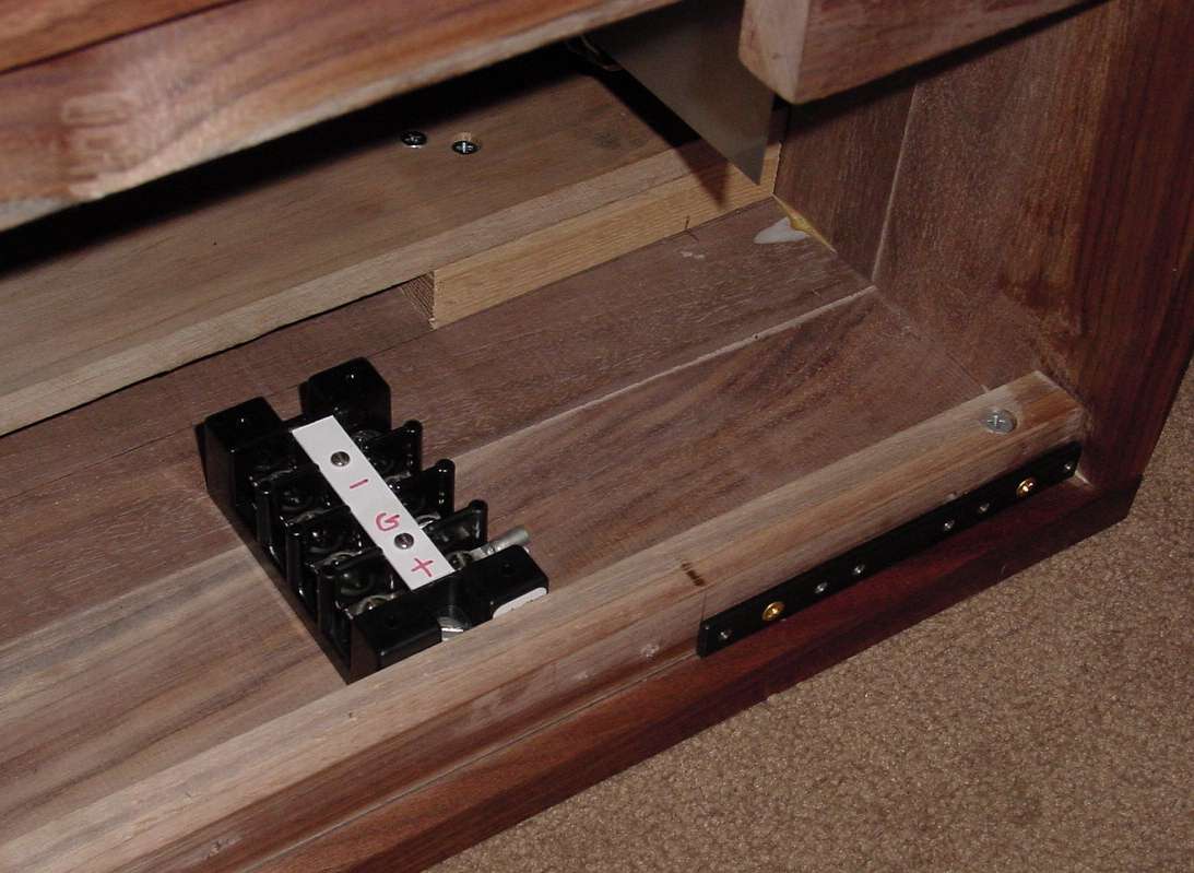
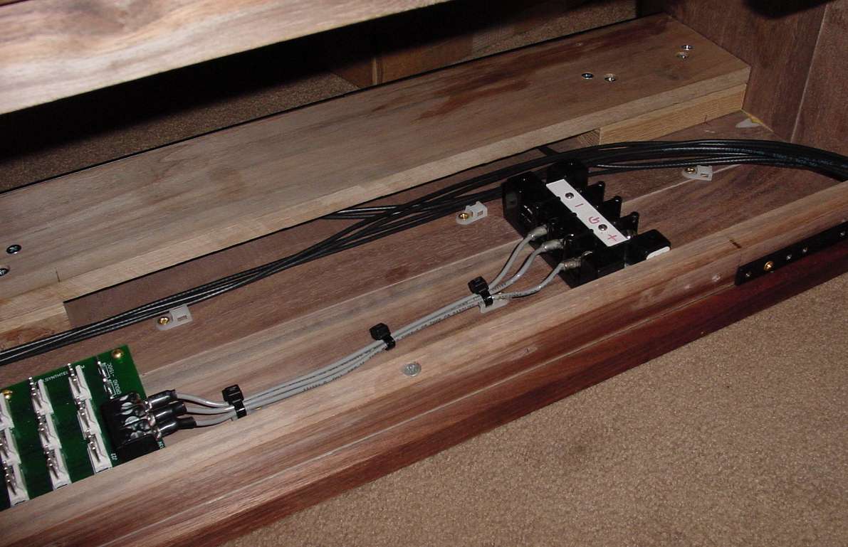
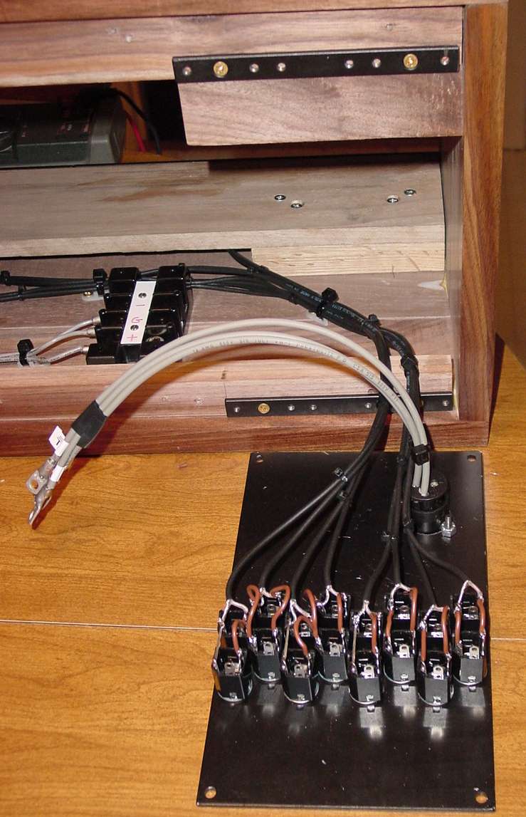
I like to have a terminal strip for DC connections. This allows me to remove the back connector plate without tugging on the PCB. These are also great for making multiple DC connections to additional PCBs.
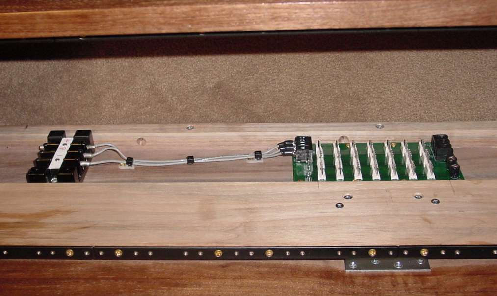
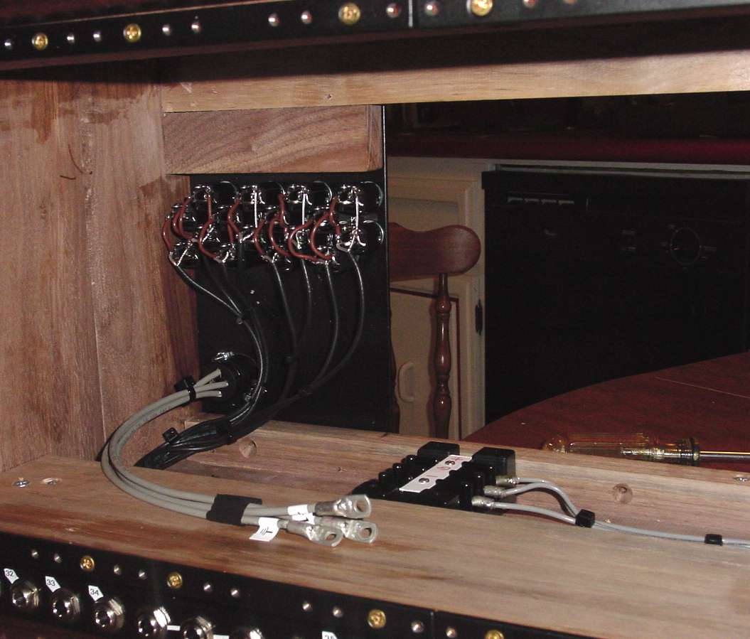
This shows the wiring from the terminal block to the PCB from the front. Notice the wire is secured to the wood at both ends.

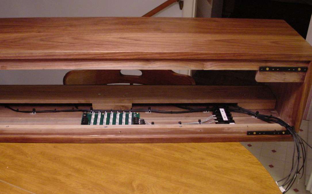
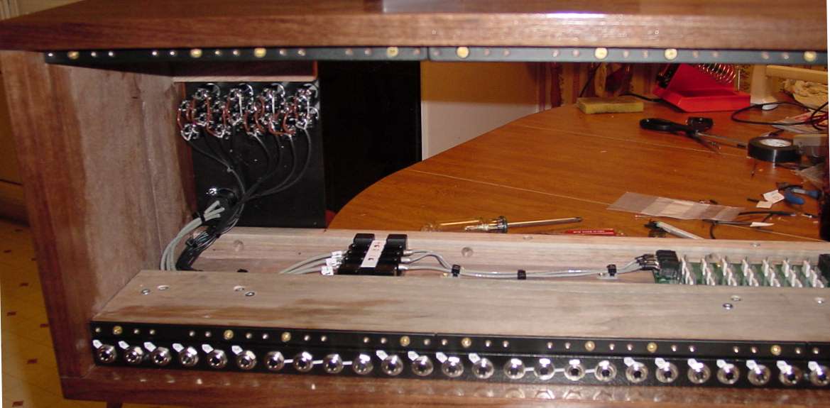
Same thing looking from the rear of the cabinet.
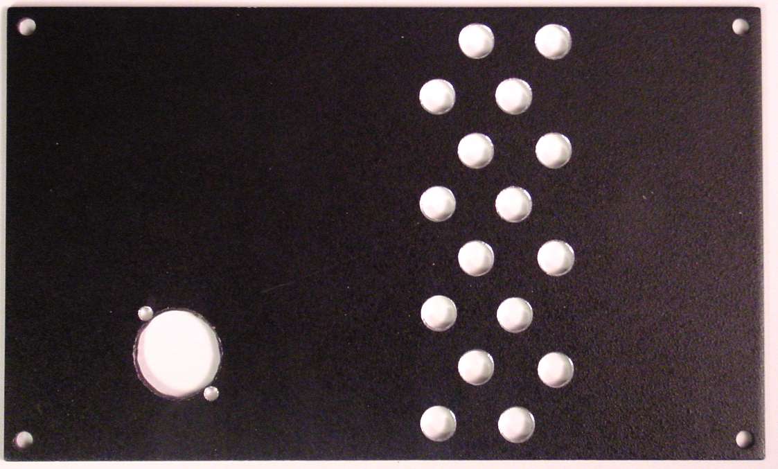
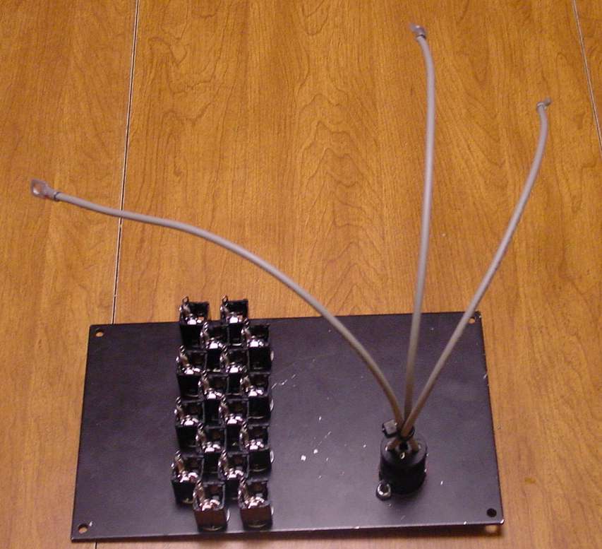
The back panel must be prepared by drilling all the holes. 16 jacks are for magic buss connection. The other is the Neutrik official MOTM DC power connector. There is no power supply inside this cabinet.
Mounting the magic bus for easy removal was a challenge. These two 1" standoffs behind the magic buss allow a machine screw from the front to hold the bus in place. I used one at each end and one in the middle.
Some of the magic bus multiples run to other jacks on other magic busses in other cabinets. The open back behind the magic buss allows the cables to fish right through to the rear panel.

All the magic bus wiring is RG-174 coax. I have tied it down with wire ties that can be easily clipped for removal or changes.
The magic bus coax runs to the rear panel where it wires to jacks for connections to other cabinets.

Magic buss jacks and power connector are added to the back. 8 multiples (A through H) are present in each magic buss.
Here’s the back of the rear panel.
Coax from the magic buss is connected to rear panel jacks just before attaching the rear panel.
Rear panel is swung up into place
and screwed to the back (flat rail cut in half). You are looking at the inside through the open front.
The connections from the power jack are landed on the terminal block. You can see how handy that is if you need to remove the real panel.
Now, we are all ready to install our modules, and simply plug their power cables into the MOTM-960 power supply distribution PCB.
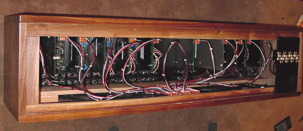
Here is the rear view prior to attaching the back. Everything is nice and neat. The power cables have been left with enough slack so modules can be removed and unplugged all from the front. We all know we are going to move them around a lot at first, and as our system grows.
The next pages show you work on the 2 row slant cabinet and its wiring. The power supply is in that cabinet.