Assembly instructions for the MOTM version of the Blacet Klang Werk
If you have decided to build the Blacet Klang Werk and convert it to the MOTM format, you have no doubt found that this procedure is more complicated than simply purchasing and building a Synthesis Technology MOTM kit. And, you have found that Blacet’s concept of "MOTM versions" of his kits is simple omission of the parts you would not use. The additional parts you need are not included. The instructions are not revised to reflect the changes involved in conversion to the MOTM format. Instead of having everything you need delivered to your door in one neat package, you must accumulate parts from a variety of sources. Here is what you need to get started:
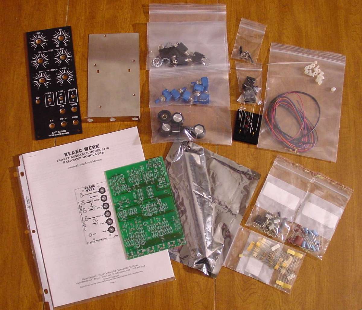
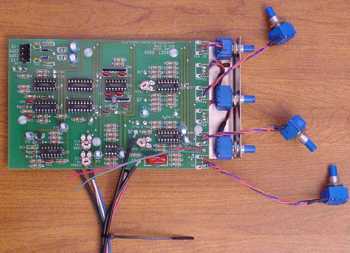
I will not attempt to list the catalog numbers here. Changes and a variety of vendors and suppliers make that task unreasonable to include in the assembly instructions. Instead, I will refer you to "the" definitive MOTM compatible parts reference assembled by Dave Bradley. Visit http://www.hotrodmotm.com/parts_list.htm for everything you need to know about where to get these parts. Here is a look at my "kit" which includes all of the original Blacet kit plus the parts I needed to add for the MOTM conversion.
You will also need to refer to your original Blacet assembly instructions for the graphics including the schematic and PCB drawings. I cannot include those in this document without infringing on John’s copyright (which, of course, I would not do).
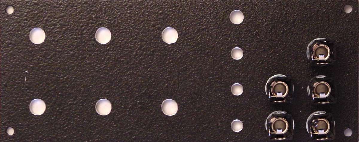
Before you begin with the electrical construction, you have some mechanical issues to deal with. My PCB mounting brackets are universal and are not specifically made for a certain PCB. Holes must be drilled in the three-pot long mounting bracket to work for this assembly. I have taken several photos of the construction process for my Klang Werk. You will find relative hypertext links to the photos throughout these instructions in the HTML and MS Word versions. If you are reading the HTML or MS Word version of this document on-line at www.wiseguysynth.com, these links will take you directly to the photos. If you have saved to your hard drive for reference, you will need to save each photo to the same directory as this document. The photo links will then work for you off-line. You can take a quick tour of all photos here. Text only readers need to view photos separately.
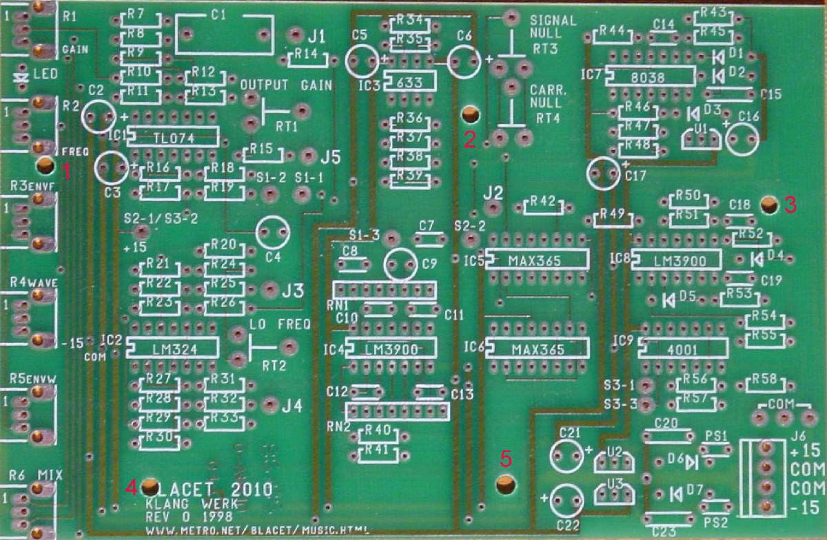
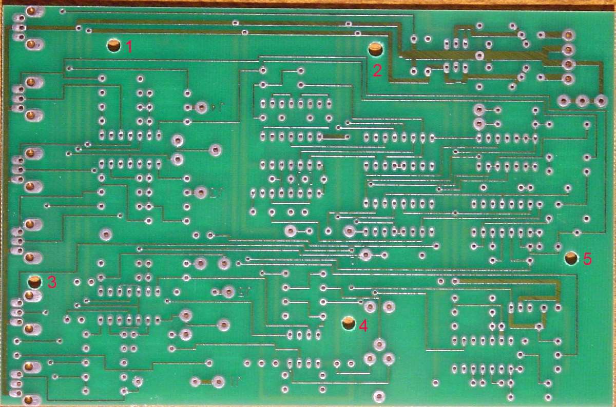
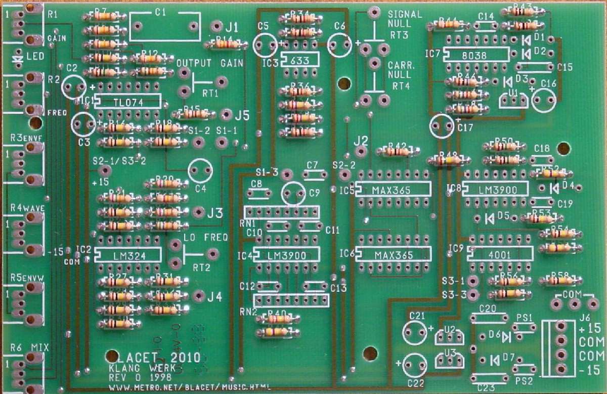
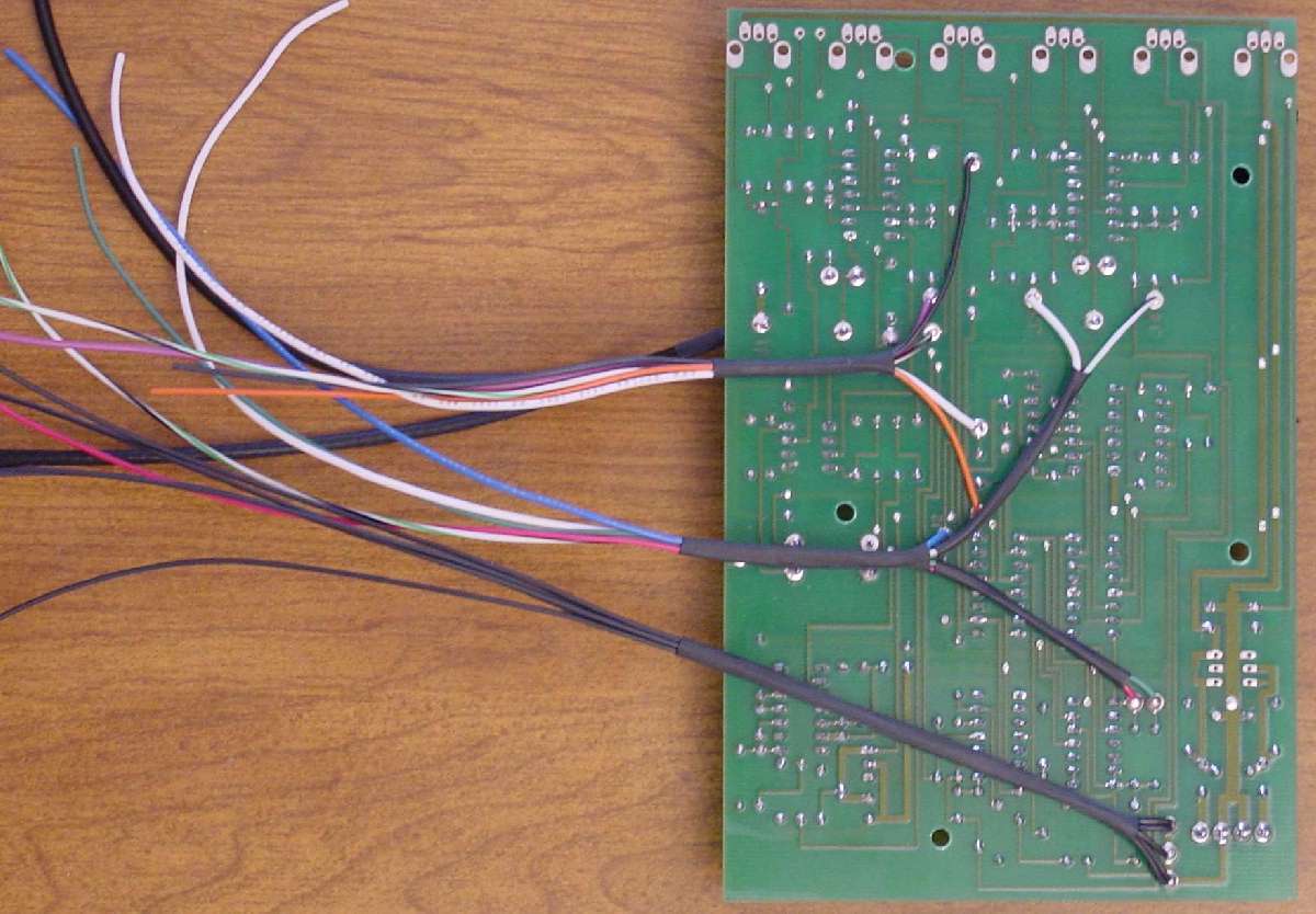
Unfortunately, the Klang Werk PCB does not include any mounting holes. You must drill your own holes in the PCB. Great care must be exercised in selecting the location of your holes. You need to be absolutely certain that no traces are cut and that the screw heads will not interfere with any parts on top. After careful consideration, I drilled 5 holes in my Klang Werk PCB for support. You can see my choices for holes in my photos of the PCB top and bottom.
Nylon machine screws, standoffs and nuts are essential as there are no locations to drill that will provide enough physical clearance for metal ones. These can be found in the specialty hardware section of most home improvement stores. I expect they can be found in many hobby stores also. I used #6-32 nylon hardware. The correct hole size for #6-32 is 9/64 inch. I highly recommend you begin with a small bit to start the hole and then drill the smaller hole out to the 9/64 finished size.
You must drill the PCB first. After you have it drilled, you can decide how you want the PCB positioned on the bracket. Then, drill the holes in the bracket that are aligned with your PCB holes. I offer the following suggestion. Place masking tap on your bracket in the general locations where you can see the holes will be needed. Position your PCB on top of the bracket exactly as you wish it to be mounted (without the stand offs of course). Don’t forget to leave room for your pots. You can take a fine point pen and trace circles inside the newly drilled PCB holes onto the masking tape. Now, you have your holes marked on your bracket exactly where they need to be. Center punch and drill your holes with the size bit appropriate for your hardware. 9/64" is perfect for 6-32.
I have my PCB on the left side (looking from the back) like MOTM modules. However, it will work either way. Putting it on the left, as I did, causes the PCB to be upside down from its original configuration. However, since no pots are board mounted, it really makes little difference. I think upside down is best actually.
This might be a good spot to make sure all your mechanical parts go together well before you move to soldering. Mount your PCB to your bracket using stand offs. Attach your bracket to your front panel using two of the three pots. Do not forget to install backing nuts on your pots. This is CRITICAL. The concept of my mounting brackets is that the bracket is held in place by sandwiching the bracket and front panel together between the back nut and front nut on the pot shaft. You cannot tighten against the pot body. You will have nothing but trouble if you try. You should always use backing nuts on your pots. Hopefully, everything fits together well in your trial run and you are ready to heat up the soldering iron.
I will confess that I have been spoiled by the completeness of MOTM assembly instructions. The Blacet instructions are not nearly as complete, leaving the assembler to search the schematic, parts list, and layout drawing to figure out what part goes where. As I write these instructions for the conversion to the MOTM format, I am also adding to the Blacet document some more specific instructions that I believe are easier to follow. I also changed the relative order of the component placement on the PCB. Here goes:
First, a word about solder. I am assuming that you will follow the MOTM solder standard and use organic solder (requiring a board wash) for much of the soldering, and then switch to a no-clean solder to complete the construction. If you adopt another strategy, you are on your own concerning the need to wash the PCB.
I like to install my components based on relative height. It seems to be easier for me. However, feel free to jump around the instructions to suit yourself. I started with the individual resistors.
PART 1: Installing the individual resistors (network resistors later)
You will use organic washable solder for this part of the construction.
All resistors are 5% tolerance resistors:
That completes the installation of all the individual resistors. This is a good stopping point for your first board wash. Run the board under warm water (do not use any soap or cleaners). Gently scrub both sides of the board to remove the organic flux. Any small brush will do the job. I use an old toothbrush.
If you have not done so already, this would be a good time to inspect your solder joints. Check to be certain you have not forgotten to solder one end of a component or that you have not accidentally bridged one thing to another with excess solder. Personally, I check my joints right before I clip my leads. It seems easier to me to find what I have just competed that way. Here is what your PCB should look like.
PART 2: Installing the non-electrolytic capacitors, diodes & resistor networks
Next, you add the diodes. Please note that 3 different diode types are used in the Klang Werk. Use care not to confuse them. And, be certain to note polarity. The arrow on the PCB points toward the stripe on the diode.
This completes the installation of all smaller sized capacitors. Do not confuse the PS1 and PS2 resettable fuse-like devices as capacitors. They resemble small ceramic capacitors but are distinguished by preformed leads and are probably marked "R010BOVS." You will install those later.
Next you will install the resistor networks. Notice that there are no PCB dots as these networks can be installed in either direction. Before you insert your resistors, check that the pins are not bent. Bend them as needed to form a straight line.
Insert and cinch resistor networks to the PCB by bending the end pins over, one in one direction and the opposite end the other direction. Then, solder a couple of pins and inspect to be sure you are happy with the position. Straighten the bent-over pins and solder all remaining pins.
OK. This is a good stopping point for your second board wash. Inspect your solder joints and be certain you have not forgotten to solder one end of a component or that you have not accidentally bridged one thing to another with excess solder.
PART 3: Installing the remaining components on the PCB
Next, you will install the IC sockets. Notice that 8, 14, and 16 pin sockets of the same width are used. Be certain not to place a shorter socket in the wrong location in place of a longer one. Also be sure to notice the PCB also indicates the end for the notch. Align the socket notch as marked on the PCB. Bending two opposite corner pins is a good way to hold the socket to the PCB wile soldering. Solder the other two corner pins ONLY. Then check the socket flat on the PCB while it is still easy to re-heat one pin and squeeze the socket to the PCB if it is not perfectly flat. Once you are certain the socket is flat, solder the remaining pins.
Next, you will install the voltage regulator and remaining capacitors (except for polystyrene capacitor C9). Polarity must be observed on the electrolytic capacitors. Notice the PCB is marked with a "+" sign. The caps have "+" indicated by a longer lead and "-" indicated by a stripe on the capacitor. Install all capacitors with the "-" stripe facing away from the "+" mark on the PCB.
OK. You are ready for your last board wash and a break. Run the board under warm water (do not use any soap or cleaners). Gently scrub both sides of the board to remove the organic flux. You will NOT use washable solder for the remainder of construction.
If you have not done so already, this would be a good point to inspect your solder joints. Check to be certain you have not forgotten to solder one end of a component or that you have not accidentally bridged one thing to another with excess solder. Verify the polarity of diodes, and electrolytic capacitors. Check that the regulator is installed with the flat side as marked on the PCB.
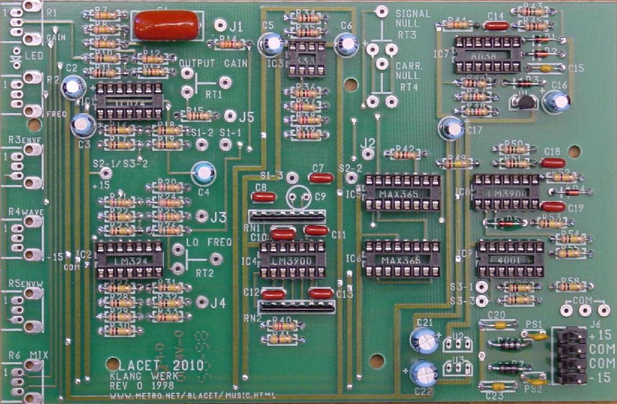
Allow your PCB to dry completely, and put away that organic solder. All soldering from this point forward will make use of no-clean solder. Your PCB should now look like this.
PART 4: Installing the trimmer pots, C9, and connecting wires to the PCB
The four trimmer pots and polystyrene capacitor C9 are the last components to be soldered to the PCB. Notice there are three different trimmer values. Be certain to get the correct value in the correct location. Check their value with your meter if you have any doubt. Don’t forget to switch to no-clean solder.
Congratulations. You are complete with all soldering of components to the PCB. Up until this point, you have basically built the PCB as if it were going behind the Blacet panel (except you did not attach the six front panel pots or LED to the PCB). From this point forward, you will be departing considerably from the Blacet version of the Klang Werk to attach to the MOTM style front panel. I will assume at this point that you already have your MOTM style front panel drilled and ready to go. I will also assume you have your bracket PCB mounting holes drilled and ready.
Your next task, is to measure and attach wires to the PCB that will eventually wire to the front panel switches and jacks. On my conversions, I have been attaching these wires to the bottom of the PCB. Kudos to Dave Hylander for this great idea. Since the PCB is double sided with plated through holes, attaching to the bottom (and applying the solder front the top) is just as easy as the opposite.
I have measured out, assigned a color and attached my wires according to the information below. Certainly, you may use different colors. But, if you follow my lead, and mark your actual colors on the instructions below, it will make attaching the opposite ends to the front panel easy. Some of the lengths I have specified may be a little long depending on how you route your wires. But, they will not be too short.
S1-1: attach a 6 inch wire – green/white/black
S1-2: attach a 6 inch wire – purple
S1-3: attach a 6 ½ inch wire – white
S2-1 / S3-2: attach a 7" wire – black
S2-2: attach a 7" wire – orange
S3-1: attach a 10" wire – red
S3-2: attach a 10" wire – green
COM (3) near the power supply connector. You can attach 3 wires here and daisy chain as per the Blacet instructions. However, I was able to get 5 wires in these 3 PCB holes without difficulty so I could have one ground wire per jack.
J2: attach a 8" wire – blue
J3: attach a 11" wire – white
J4: attach a 11" wire - green/white/black
Notice J1 and J5 do not get wires attached. I used coax for these connections.
This is the end of the wiring I attached to the bottom of the PCB. The remainder of the connections I attached to the top side.
LED (between R1 and R2) attach two wires 5" long of different colors.
J1: attach a 6" piece of RG-174 coax
J5: attach a 7" piece of RG-174 coax
There is no connection point at the PCB for the J1 and J5 coax shield. You will connect the opposite end to a ground wire when you connect the jacks to provide the shielding. At the PCB end, simply trim back and remove the shield about ½ inch so it will not short against the PCB. I used a little heat shrink on mine.
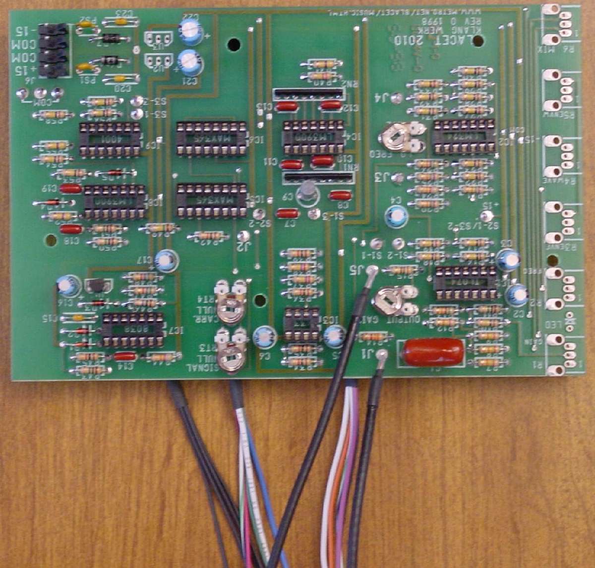
This completes all soldering to the PCB. Your completed PCB should look something like this. On the bottom side, I recommend grouping your wires (no wires the same color in any group except common), into heat shrink. This keeps your wires secure and neat. The heat shrink also protects the wire insulation from the sharp cutoff component leads. Here is how mine turned out.
Your next task, is to prepare the front panel pots for attachment to the PCB. Gather up your six 50 K linear pots. I prepared my front panel pots by attaching all the wires of the correct length to facilitate the attachment to the PCB. I also decided to adopt a color standard for the pot terminal numbers. I highly recommend this. Throughout the remainder of these instructions, I will often refer to the colors I used. You may select different colors. But, please write down your color strategy.
For my standard for pots, I elected to use these colors: Pin 1 = blue, Pin 2 = purple, Pin 3 = orange. Please be aware that all of the wire lengths I specify in this document assume a PCB mounted to the left (looking from the back). Opposite side mounting will change these recommended lengths.
First, attach three wires to each 50 K panel pot. Be sure you have a backing nut for all six of the pots. If you use pots intended for PCB mounting (as I did), use heat shrink to insulate the wires connected to the pots.
You may wish to leave the leads about one-half inch longer for trimming and stripping the ends for soldering. Your pots should look something like this.
Part 5: Attaching pots to the PCB and mounting to the front panel.
First you will connect the pots to the PCB. Be certain that the terminal numbers on the pots match those on the PCB. Notice that terminal 1 is marked at each pot location. Following my color standard, blue goes to 1, purple to 2, and orange to 3 for each pot.
If you have not done so already, twist the pots around so that all the leads between the PCB and the each pot are neatly twisted together.
Next, you will mount your PCB to the bracket to prepare for front panel mounting. Make certain that none of your wires on the bottom of the PCB are broken or shorting against anything. Use the 5 sets of nylon screws, spacers, and nuts to mount our PCB to the bracket. Be careful not to overtighten the nylon nuts. Once you get your PCB attached to the bracket, it should look like this. You may notice that in my photo the pots are not in the correct location for the bracket mounting. These instructions later are specific as to which pot goes in which position.
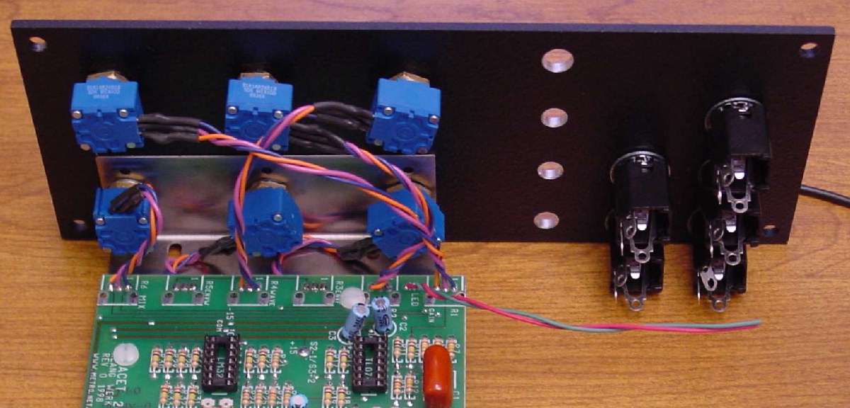
Before, you mount your PCB and bracket to the front panel, I suggest you attach your jacks to the panel. You may wish to install your switches too. The switch orientation does not matter as I will refer to top, middle, and bottom when attaching the wires. However, be certain to put the center-off switch in the "Y SHAPE" position.
The bracket with PCB attaches to the front panel with the pots. Three of the pots will hold the PCB mounting bracket to the front panel. I am assuming you are following my lead to have the PCB on the left side as you look from the back (MOTM style). Adjust accordingly if you have selected the opposite side. Be absolutely certain to use the backing nuts on your pots. You cannot tighten against the pot. This will ruin the pot.
Before tightening these pot nuts to secure the bracket, be certain to align the bracket to your satisfaction. I recommend aligning the bracket edge (where it is bent) up straight with the panel front edge and set back inside about 3/16 inch. One method is to place the bracket flat on a table with the panel "edge" against the table to line everything up straight. Once you are satisfied that the bracket is lined up to your satisfaction, tighten the three pot nuts on the front of the panel. Use a nut driver to avoid scratching the panel.
Tighten all 3 pot nuts on the front of the panel. Use a nut driver to avoid scratching the panel. You may notice two of the pots are unintentionally reversed in my photo. And, here is another view of the attachment. Please follow the instructions for location and "pay no attention to the man behind the curtain."
Part 6: Completing wiring of switches, jacks, and LED to the front panel.
First, you will connect the PCB wires to the switches. I will refer to my selected colors. Please mark your instructions to reflect the color choices you made to avoid mistakes.
First the "EXT Y" AC/DC switch 1:
Next wire the "Y SRC" INT/EXT switch 2. You will need a short wire jumper about 3 inches long when wiring this switch. I used black:
Next wire the "Y SHAPE" 1/2/3 switch 3:
Next, you will wire the jacks. You have 5 long black wires attached to the "COM" point on the PCB by the power connector. These are all attached to the same point, so it does not matter which one goes to which jack. I twisted three of these wires (one each) together with the three remaining wires I have left (except the coax) to create twisted pairs to go to the panel jacks. All instructions assume you have installed the jacks with the bevel corner at the upper right (looking from the back).
You now have everything wired to your panel except the LED. The polarity of the LED must be observed. Look on page 6 of the Blacet instructions for a drawing relating the LED lead length to the electrical connection. The Anode is always the longer lead on LEDs that have different lead lengths (most all I have ever seen). The flat side of the case indicates the cathode. Insert your LED into the panel from the front. Then, connect your PCB wires as follows:
I recommend shortening the leads on the LED prior to wire attachment and using some heat shrink to insulate the connection. Once the LED is wired, you probably have enough slack in the wiring to pop the LED out the front of the panel and "carefully" twist the leads coming from the PCB. Once complete, your Klang Werk module should look something like this.
Insert your chips into their sockets. Take care to get the chips in the correct sockets and with the notches all facing toward the front panel. Use small wire ties to secure the wiring to your front panel jacks and switches as appropriate.
Congratulations. Your Klang Werk module is now completed. Add your six knobs to the panel pots. Your Klang Werk is now ready for testing and calibration. Please refer to the Blacet documentation for testing and calibration.
That concludes my instructions for assembly of the Blacet Klang Werk module in MOTM format using Stooge panels and brackets. I hope my work has made the process more enjoyable for you and helped you to achieve success. I always welcome feedback and constructive criticism. If you have any ideas for improvement of this document, please drop me a note. Here is a completed photo.
Larry Hendry
KW2010
01/07/03 - Revision 0