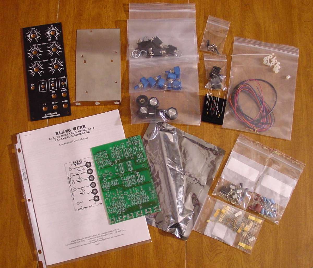
I have everything I need assembled. That includes the Blacet kit, and my add on parts for MOTM format conversion (front panel, bracket for PCB, jacks, knobs, and pots).
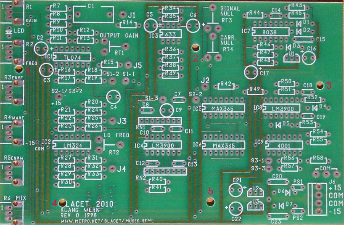
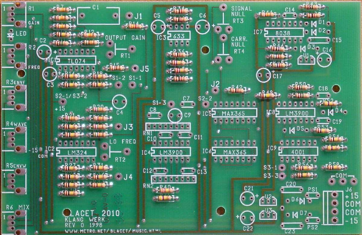
Here is the top of the Klang Werk PCB. It is a quality PCB – double sided, solder mask, plated through holes. It’s a real joy to solder.
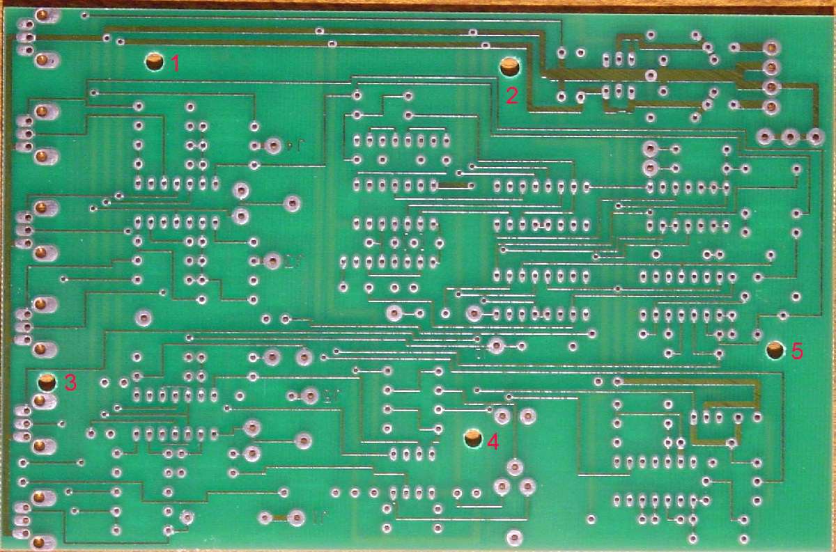
And, the bottom is also nice.
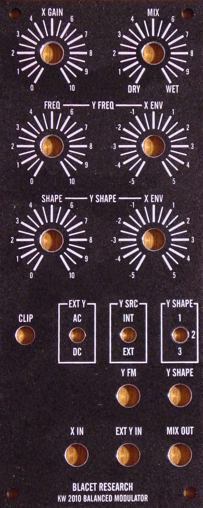
Here is the Stooge panel for the MOTM conversion. Some of the nomenclature is changed to reflect standard MOTM identification.

The PCB fits well on a Stooge 3 pot long bracket. Some drilling required of the bracket and PCB are needed. Check out my complete detailed instructions for the assembly and conversion of this module.
# 6 Nylon machine screws, nuts and spacers are needed for mounting the PCB to the bracket.
I soldered the resistors first.
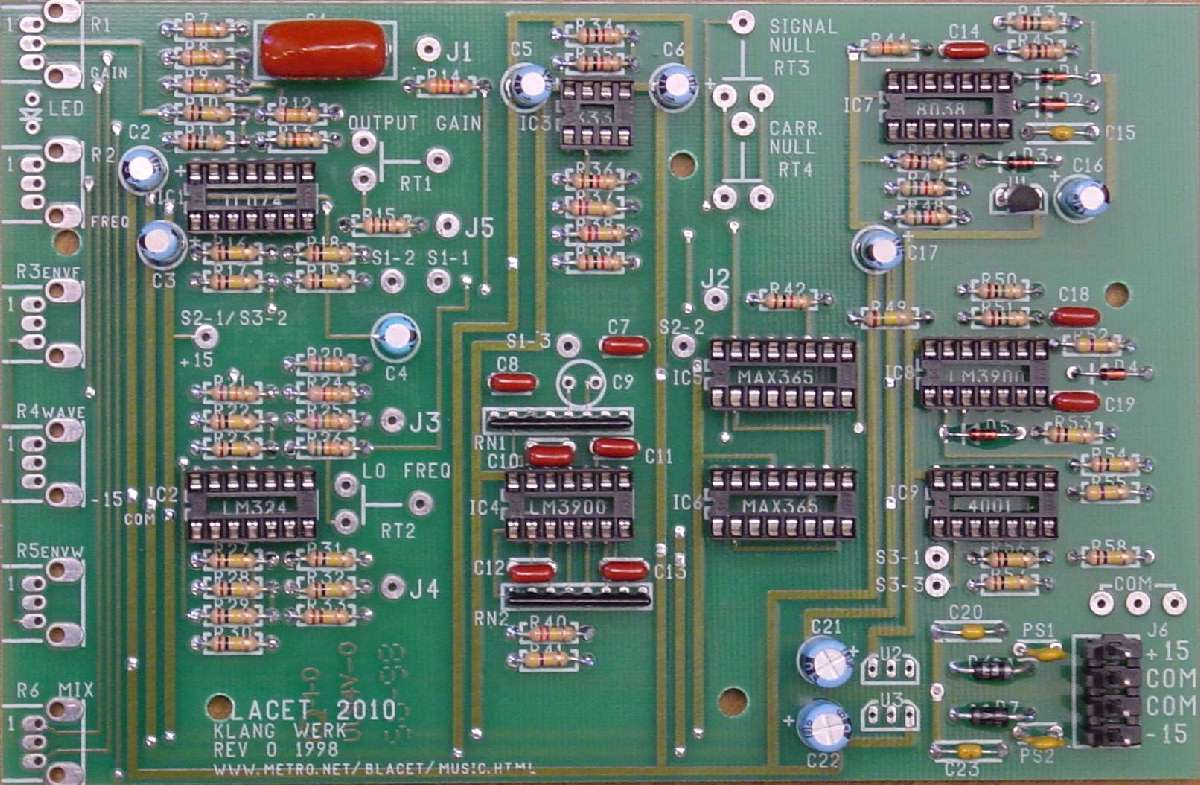
And, here is the PCB with all other parts that can be attached with washable solder.
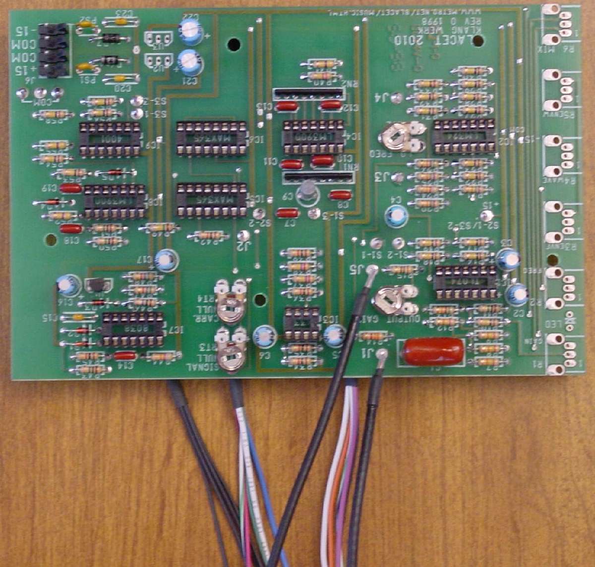
The PCB is completed except for pots by soldering all the wires for front panel connections.
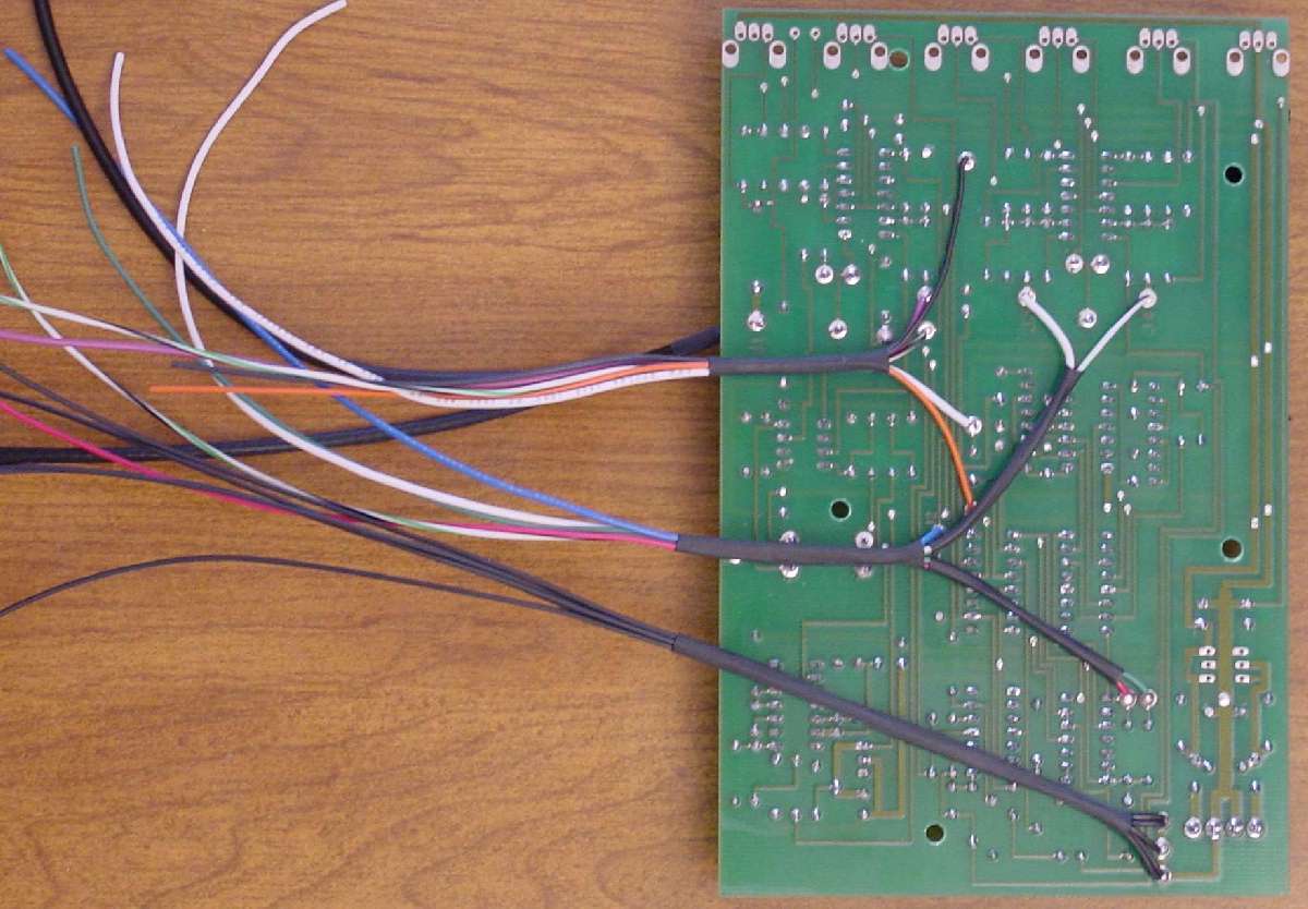
To keep the module neat, I ran my wires under the PCB and used heat shrink to keep them neat and protect them from puncture from sharp cut-off leads.

The last attachment to the PCB will be the pots. Here they are prepared with correct lengths of wire and heat shrink.
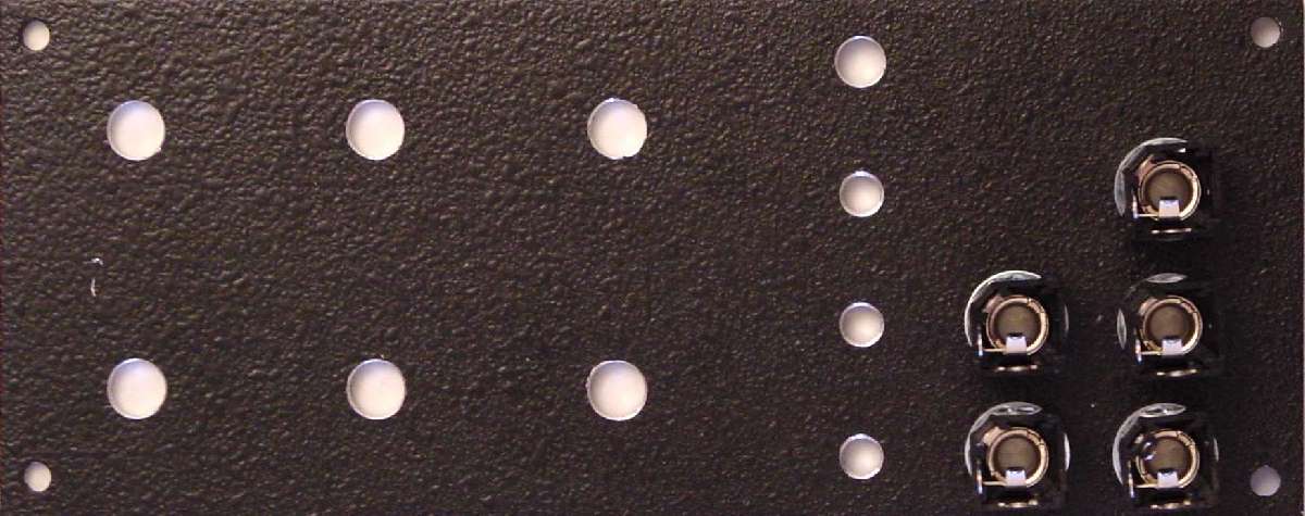
The panel must also be prepared by mounting the jacks in place.
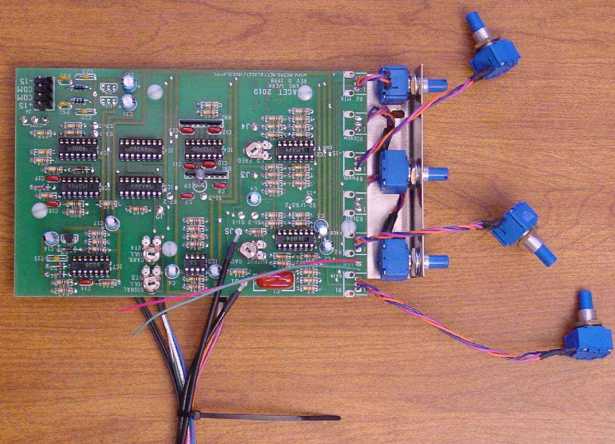
The prepared pots are attached to the PCB and then the PCB is mounted to the bracket.
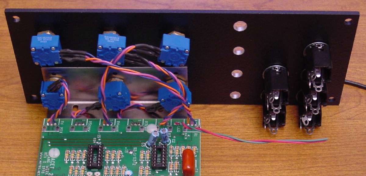
The PCB and bracket are attached to the front panel using the pots. Note a pot nut MUST be used front & back.

With the PCB attached, and the other three pots mounted to the front, we are ready to wire the switches & jacks.

The jacks, switches, and LED are wired. Small wire ties keep the wires neat and in place.

Here is the completed front. It matched up with your MOTM modules perfectly. J