My day gig
– New Updated 2/16/04 (updates in blue)
When I am not messing around with modular synths or shipping parts for synth builders
around the world, I have a regular job. Like most musicians, I call it my day gig. I have
worked for an electric utility company in the Midwest, USA for over 27 years. I am what
is called a "high-voltage specialist." So, while my synth circuit abilities are somewhat
limited, I am well versed in the operation of high voltage AC circuits.
|
|
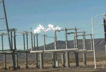
The photo to the left will link you to an amazing video (~1.5 Mb) of a ½ million volt switch failing to interrupt the arc when operating. Special thanks to Old Crow for hosting this popular video. If you are interested in some light technical analysis of what you are looking at, see the text below this photo. |
I was not given the details of this clip when it was sent to me.
However, a couple of
days ago, I received an e-mail from the person actually running the video camera.
He basically confirmed my analysis of the switch operation and a few other details.
Based on what I do know about the equipment in the video, what I see,
and now what
has been reported to me first hand, I offer the following info:
The video was taken at Eldorado Substation in Boulder City, NV. The file is called
Lugo because this switch and shunt reactor are on the line that goes to Lugo.
This
one is clearly a 500KV (I can tell by the size) three-phase switch, probably rated at
about 2000 amps of normal current carrying capability. 500 KV refers to the phase-
to-phase voltage. Divide by 1.732 to get the phase-to-ground voltage (289 KV).
This type of switch typically is used at one end of a transmission line, in some cases in
conjunction with or instead of a circuit breaker for a variety of different configuration
reasons that vary greatly from one utility to the other. Or, it may be used to connect a
large transformer to the system.
In this case, the switch is being used to connect a special kind of transformer. The 3
single-phase transformers can be seen behind the truck. I say transformer, but as you
can see, they have leads going in, but not coming out. These are actually single winding
inductors connected from phase to ground and are commonly called "shunt reactors."
These inductors are installed to offset the capacitive effects of un-loaded transmission
lines, When a long 500 KV or 765 KV line is energized from one end, its inherent
capacitance causes an unacceptable voltage rise on the open end of the line. The
"shunt reactor" is installed to control that open-circuit voltage. Where current into the
capacitor component of the line impedance leads voltage by 90 degrees, current into
the shunt reactor lags voltage by 90 degrees. I have since learned that these shunt
reactors are rated at 33.3 MVAR each to make up a 100 MVAR bank.
The switch being opened is called a "circuit switcher." It consists of two series SF6
gas puffer interrupters (similar to a circuit breaker) and an integrated center-break
disconnect. The interrupters are to the right of the switch blades. They just look like
gray porcelain insulators. At 345 and 500 KV these types of switches typically have
two interrupters per phase in series in order to withstand the open circuit voltage
encountered when de-energizing a line or transformer. They rely on synchronized
opening of the two interrupters and voltage even distributed across the two interrupters
by "grading" devices (typically lots of series capacitors or resistors).
The way they are supposed to work is the interrupters both trip, grading capacitors or
resistors cause the open circuit voltage to split evenly across the two interrupters, the
switch blades open with no current flow, and the interrupters close as the switch
reaches the full open position. I originally titled this very BIG capacitor because that
is what unloaded transmission line looks like. The parallel wires have a huge capacitive
effect between ground and each other. On a 500KV line like this the current (leading the
voltage by 90 degrees) required to energize this capacitor is approximately
1.8 amps
per-mile of line per phase. That's 1.8 amps per phase at 289KV, or about 1.56 Mega
Vars (million volt amps reactive) per mile. However, we are actually looking at the shunt
reactor current which is inductive and lags the voltage by 90 degrees. So, I should have
said "very big inductor."
The switch operation you see in this video in my opinion is a failed attempt to interrupt
that inductive current. The failure appears to be that the far right interrupter does not
open or the grading device has failed. The voltage across the remaining open
interrupter exceeds the rating and it flashes over (you can see the first arc develop
across one interrupter). Therefore, the switch blades are left to interrupt the current (not
designed to do that) as they open. As the interrupter closes you can see the arc across
it go out. However, the arc across the switch gets as tall as a 3 story building. The arc
is extinguished only when the circuit breaker energizing the line, circuit switcher, and
reactor is opened by the operator. Because some trouble was expected on the
switch, arrangements had been made ahead of time to trip open the circuit breaker if
necessary. This is the only failure I have ever seen where the arc lasted so long and
grew so large without first going phase-to-phase or phase-to-ground taking the circuit
out of service. It just keeps growing straight up where it contacts nothing.
Since I have seen many people speculate as to the amount of current in the arc, I will
offer the actual calculations that are based on the assumption that the switch is only
interrupting the current into the shunt reactor and the second hand report I received
that this is a 100 MVAR reactor bank. Let’s look at only one phase:
33,300 KVAR divided by 289 K Volt = 115.2 amps.
I was told by the person who took
the video that the current was "about 100 amps."
I hope you enjoyed the show.
back to main menu