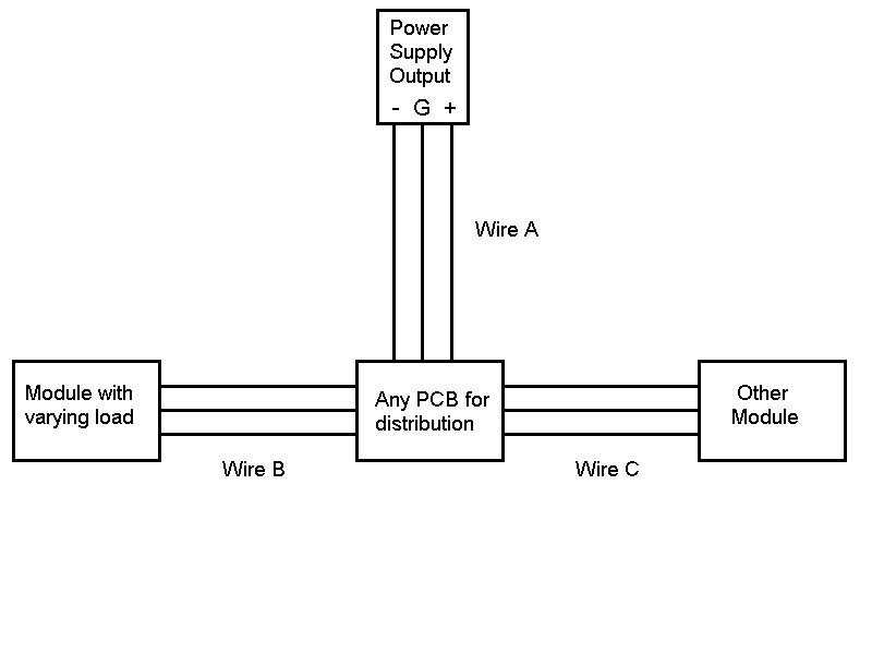
Ohm's law tells us that anytime we have current flow across resistance, we have voltage drop. We
know that all the components of our power supply wiring have resistance. We are going to look at
ONLY the resistance of the wire. If we look at the drawing, we can assume that the voltage at the
PCB is lower than the voltage at the power supply by this amount:
E drop (wire A) = I (module left) + I (module right) x R (wire A).
The voltage at each module is also lower than the voltage at the PCB by this amount:
Module left:
E drop (wire B) = I (module left) x R (wire B)
Module right:
E drop (wire C) = I (module right) x R (wire C)
To find the voltage drop in the wiring to each module from the point of regulation (the power supply),
we have to add the voltage drops:
For module left total drop from the power supply:
E drop (wire A) + E drop (wire B)
For module right total drop from the power supply:
E drop (wire A) + E drop (wire C)
About now, you are probably cursing me for stating the obvious. But, I wanted it to be clear that current
from one module effects the voltage delivered to a different module.
See that voltage drop to module right = [I (right) + I (left) x R (wire A)] + [I (right) x R (wire C)]
And, varying current produces varying voltage drops. So, in our example, we see that varying load in
module left is causing varying voltage to be delivered to module right. That is going to occur, no matter
what we do with wiring. Our task is to minimize that to a negligible amount.
Since we have only 2 modules in the drawing, I am going to put some out-of-proportion numbers in
the formula to make a point.
module left I minimum = 20 mA; maximum = 50mA
module right I = constantly around 30 mA
Voltage (+15) we will look at only one leg
resistance wire A, B and C all = 2 ohms
Voltage at PCB (I left min) = 15 - [(0.02 + 0.03) x 2] = 14.9 volts
Voltage at module left = 14.9 - (0.02 x 2) = 14.86
Voltage at module right = 14.9 - (0.03 x 2) = 14.84
Voltage at PCB (I left max) = 15 - [(0.05 + 0.03) x 2] = 14.84 volts
Voltage at module left = 14.84 - (0.05 x 2) = 14.74
Voltage at module right = 14.84 - (0.03 x 2) = 14.78
Delta E module left = .12 volts (.08%)
Delta E module right = .06 volts (.04%) 50% of delta E (left)
So, even though module right has a constant load, it is seeing a fluctuating supply voltage because of the
varying voltage drop across wire A caused by the varying load of module left. The problem is that wire A,
B and C all have the same resistance. So, voltage drop from each module is imposed equally across its
own power cable and the power cable that supplies the PCB (wire A in this case).
The solution, is to lower the resistance of wire A so that a larger percentage of the varying voltage drops
is found across the individual module power supply wire. Interaction between modules is then reduced.
Let's change the resistance of wire A from 2 ohms to 2/10 ohm and look at these numbers again:
Voltage at PCB (I left min) = 15 - [(0.02 + 0.03) x 0.2] = 14.99 volts
Voltage at module left = 14.99 - (0.02 x 2) = 14.95
Voltage at module right = 14.99 - (0.03 x 2) = 14.93
Voltage at PCB (I left max) = 15 - [(0.05 + 0.03) x 0.2] = 14.984 volts
Voltage at module left = 14.984 - (0.05 x 2) = 14.884
Voltage at module right = 14.984 - (0.03 x 2) = 14.924
Delta E module left = .066 volts (.044%)
Delta E module right = .006 volts (.004%) 9% of delta E module left
Notice how lowering the resistance of the wire A has reduced the delta E to module right caused by the
varying load of module left. Or, to say it more easily, module interaction due to power supply coupling has
been reduced. Now, these numbers are a little out of whack as the resistance of our power wires was
exaggerated some to make a point.
But, now we see the importance of using LARGE wire between the power supply and the distribution
PCBs. This wire should represent the smallest portion of resistance in the wiring between the power
supply and the module. I always use # 12 or 14.
This question comes up frequently, and I hope this helps someone understand why the wire to the distribution point has to be sized for something other than it loadability.
