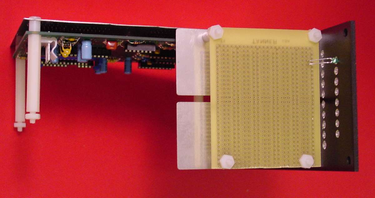
This shows the position of the CV PCB on the Miniwave module. The location was chosen to allow all 18 (8 miniwave + 10 expander) LEDs to be mounted on a PCB.
You can see from this angle that three stooge brackets are used for all PCB mounting. And, stand-offs are in place to support Hylander’s PROM expander board above.
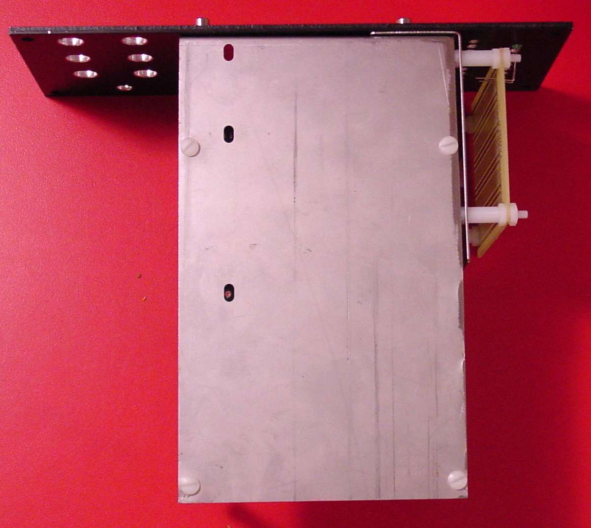
From the back side of the bracket, you can see I have used a 4-pot long bracket and I have cut the size down some. A 3-pot bracket could be made to work without cutting. But, a 4 pot bracket is recommended to use the Miniwave PCB mounting holes. Two new 1-pot mini brackets are used to hold the CV PCB.
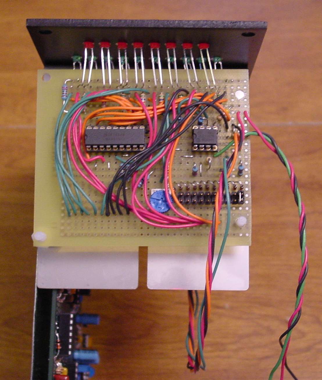
This photo shows the protoboard mounting from the top. When the PCB is actually made, it will be slightly deeper and will fit closer to the panel to keep the LED leads as short as possible. Headers along the back will provide connections for power and the other PCBs,
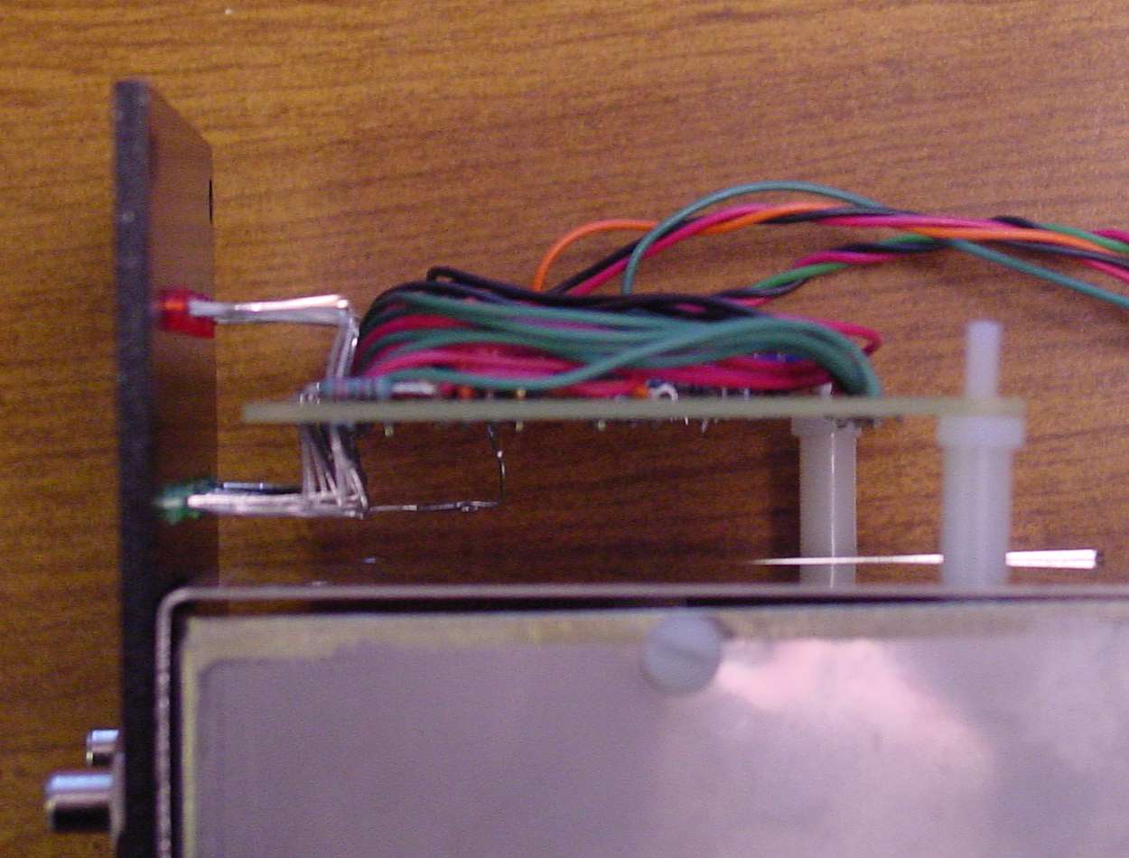
From the side, you get a feel for how the LEDs will mount. Of course, the leads will be shorter, but the 90 degree bend provides a lot of flexibility in alignment when installing. A slight "over-bend" will assure that the LEDs are kept firmly in place on the panel.

Here I show my Miniwave PCB completed with panel wiring ready to be placed on the bracket. I like to bring some of the front panel wiring out from underneath the PCB to keep everything neat. The jack wiring (on the right of the PCB) gave me a nice place to secure my LED ribbon cable
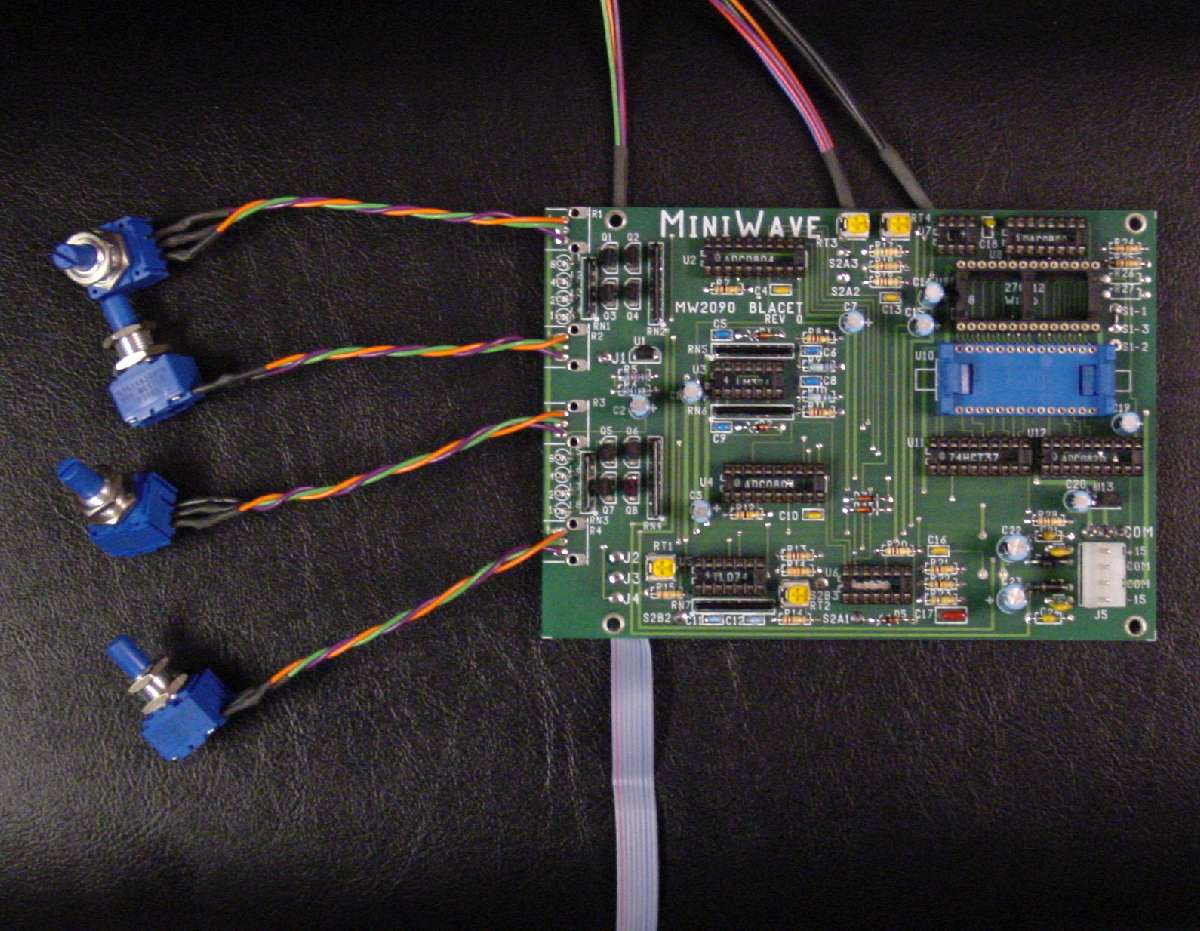
Here’s what the completed Miniwave PCB looks like from the top. The only modification required to the PCB is to omit two resistors and install one jumper from S1-1 to S1-3 as you will not have an A/B switch. I also recommend not installing the Blacet supplied leaf spring ROM socket. This is where the cable will plug. It holds MUCH more securely if a machine socket is used. I already had mine installed before I realized this.
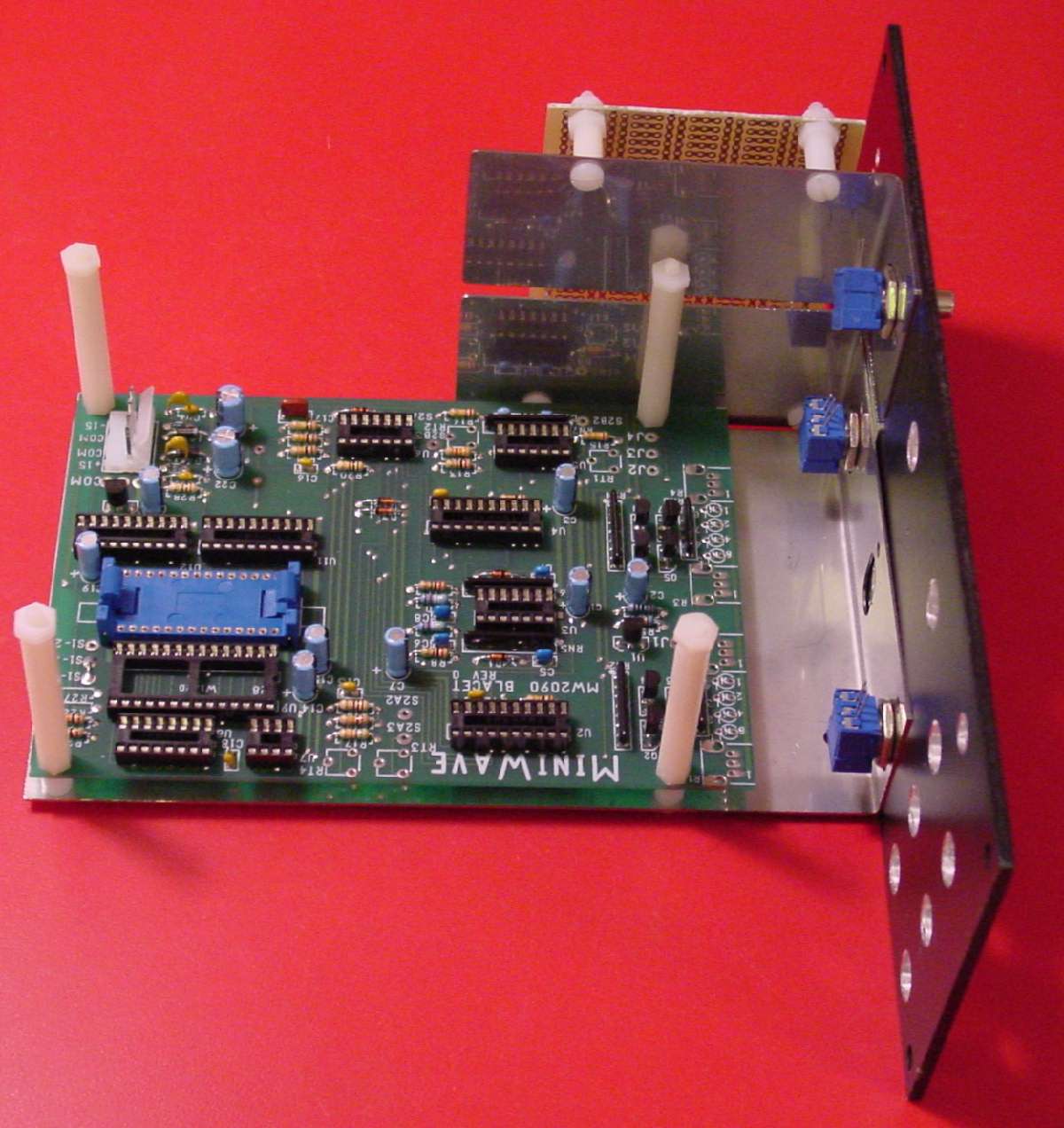
The Miniwave PCB is mounted on the bracket. The 3 of the 4 pots hold the brackets in place. Another pot is added to that task when CV PCB is installed.
All the loose ends of the panel wiring are completed. The yellow wire looking out of place is a temporary OUT(-) connection. Please ignore.

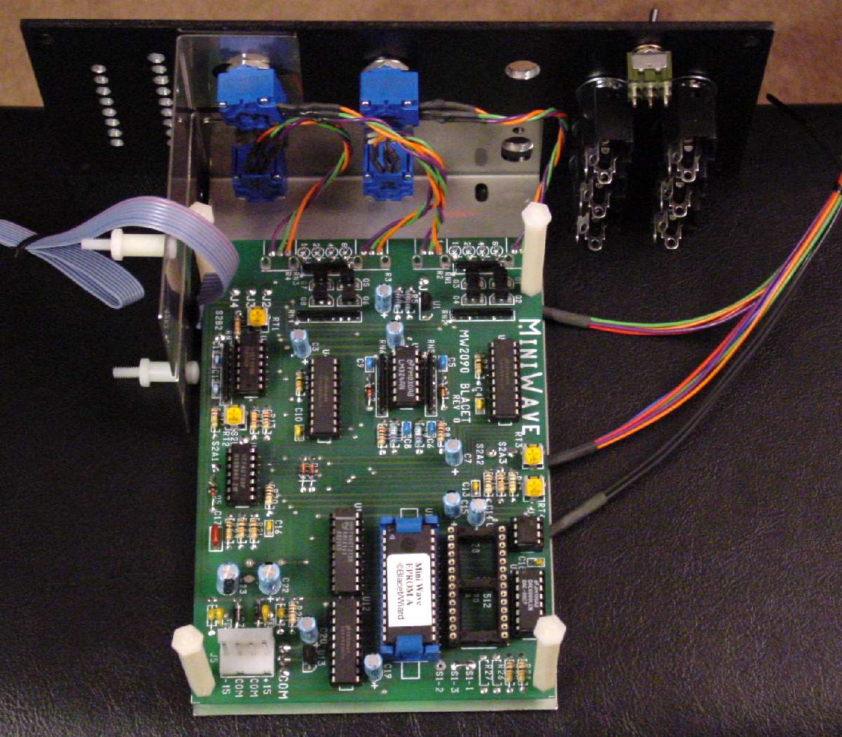
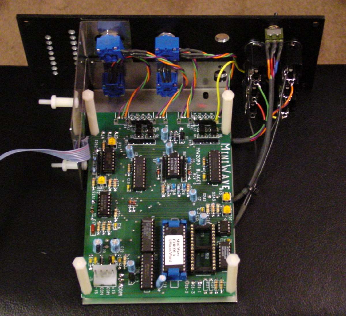
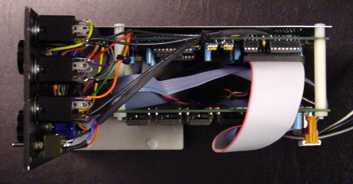
Once the CV board and the PROM expander board are installed, your Miniwave will look something like this. Of course, the CV board will be a lot nicer than my proto version. A ribbon connects the Miniwave to the PROM expander. A power cable connects up to both Miniwave and expander. The CV control PCB will get its power from a connection on the PROM board.

Here is a look from the top. I have a lot of excess ribbon cable length in mine going to the CV PCB. I will shorten this up when I get the official PCB. The CV PCB will have one ribbon to the Miniwave (for the LEDs) and one to the expander PCB. A small number of wires go to the front panel.
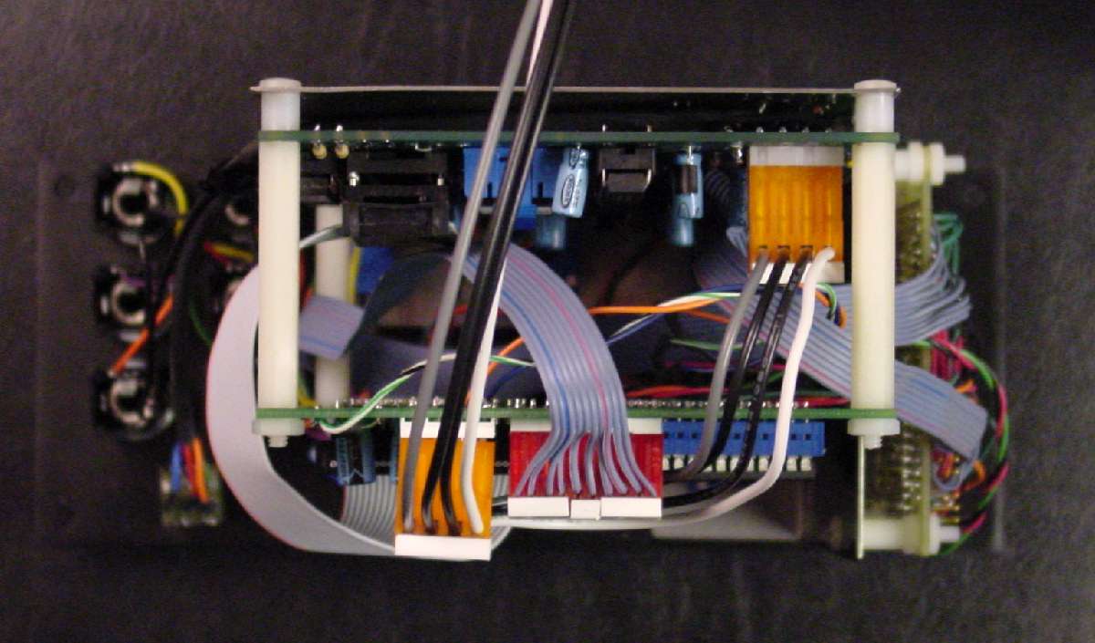
Here’s a look from the bottom. There’s a lot of stuff in there. However, great care has been taken by all involved in this project to make sure all the mechanical fit issues were considered.
Here is a photo of the completed module from the back. You can notice a couple of things. First, notice that the stock Miniwave PROM is not located in the socket John intended. Instead it is installed in the LIF socket. The ribbon cable connects to the original PROM socket. I already had my leaf style socket installed on the Miniwave PCB before I discovered that the connecting cable holds much tighter if a machine socket is used. I did not want to de-solder it and risk my Miniwave PCB. If you find yourself in this same situation, you can do what I did. I plugged a machine socket into the leaf socket and plugged my cable into that. It really works great. J

Here is the completed view from the front. I plan to change the LED colors on the final version – 4 red, 4 green for bank and wave, 10 blue or orange for PROM select. Notice you have two new pots for CV select of the PROMS. They function exactly the same as the Miniwave pots for bank and wave. Also notice the OUT (-) jack. That inverted out is a new feature for the Miniwave supported on either the PROM expander or the CV board.
New:
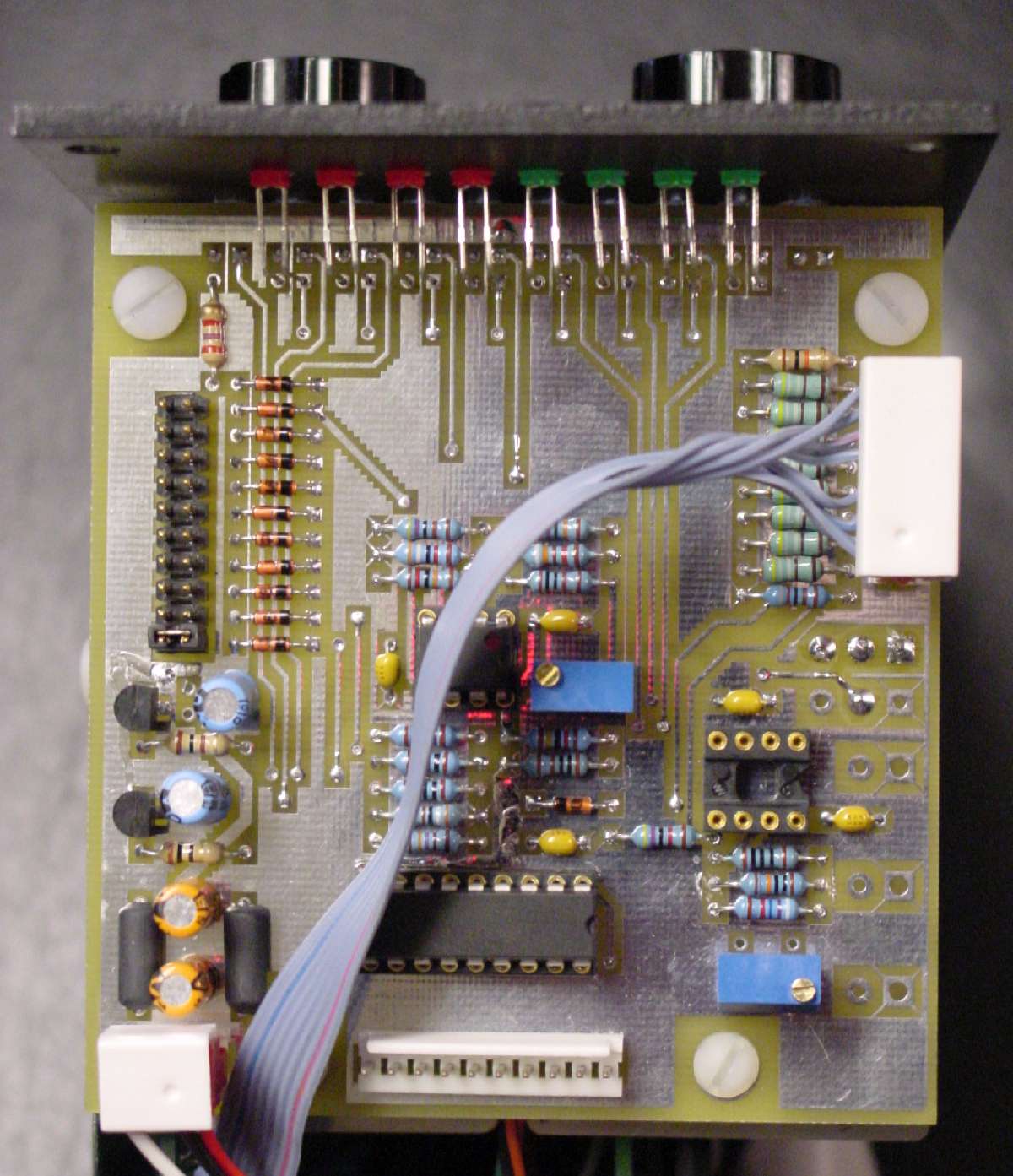
This is the new PCB that made by Scott Juskiw. The final product will be solder mask and silk-screened. This is the "test" PCB to make certain all is OK for production. The empty IC socket is for the inverting op amp that will supply the OUT(-). That same circuit is also available on the new version of the Hylander PROM expander. So, you have your choice on which to populate and use.
The connector at the bottom connects to the Hylander PCB. The connector with the ribbon cable connects to the main Miniwave PCB to supply the connections to the LED drivers. To make it easier to build, we included all the LEDs on this PCB. That takes in the 10 new LEDs for the PROM select (bottom of PCB) and the 8 to show wave and bank. You are not required to do it this way. But, trust me, you will want to. The jumper selector on the left is where you set the number of PROMs in your Miniwave. This limits the sweep to only those PROM sockets that are actually populated.