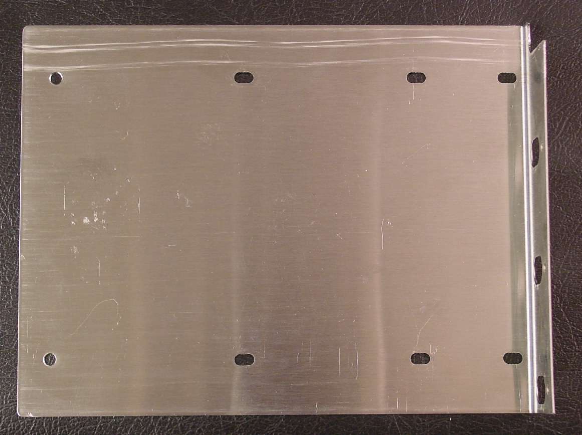
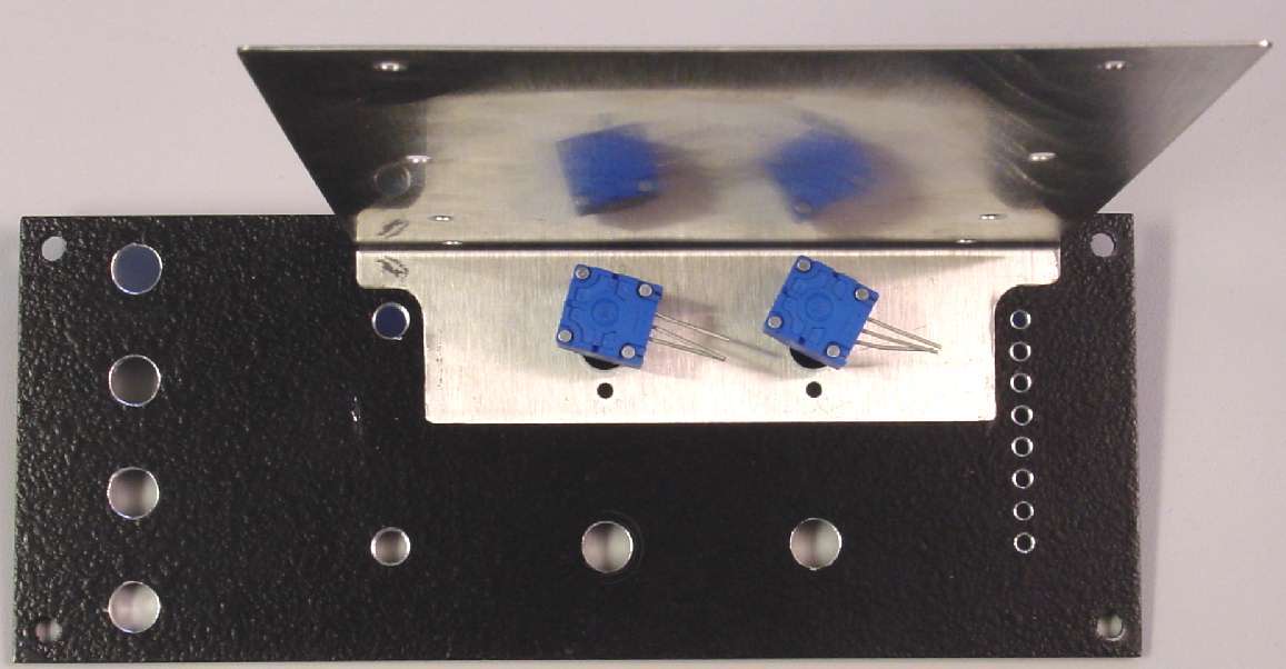
4 pot bracket with two extra holes drilled at back for PCB mounting

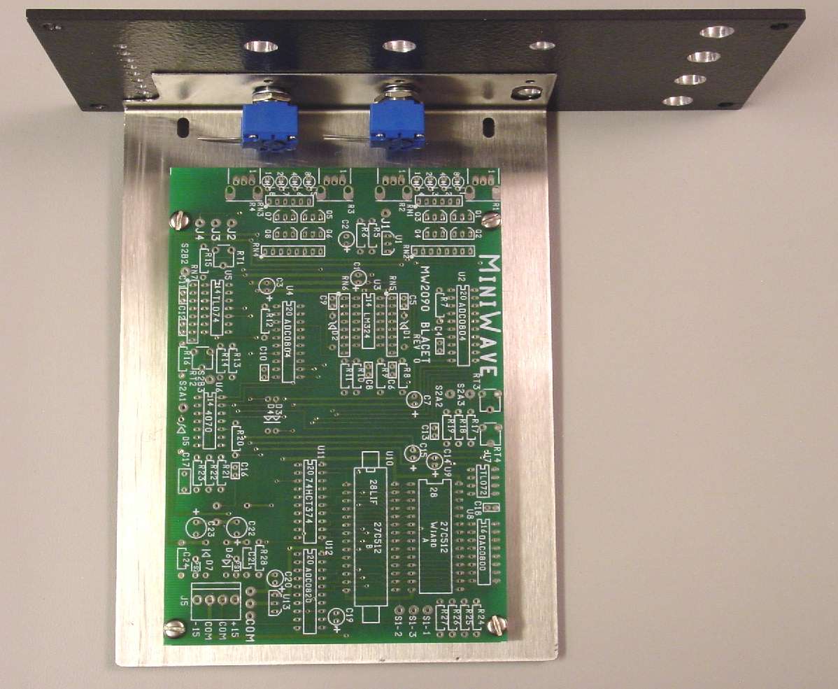
PCB at the end of step 2. Organic soldering is complete
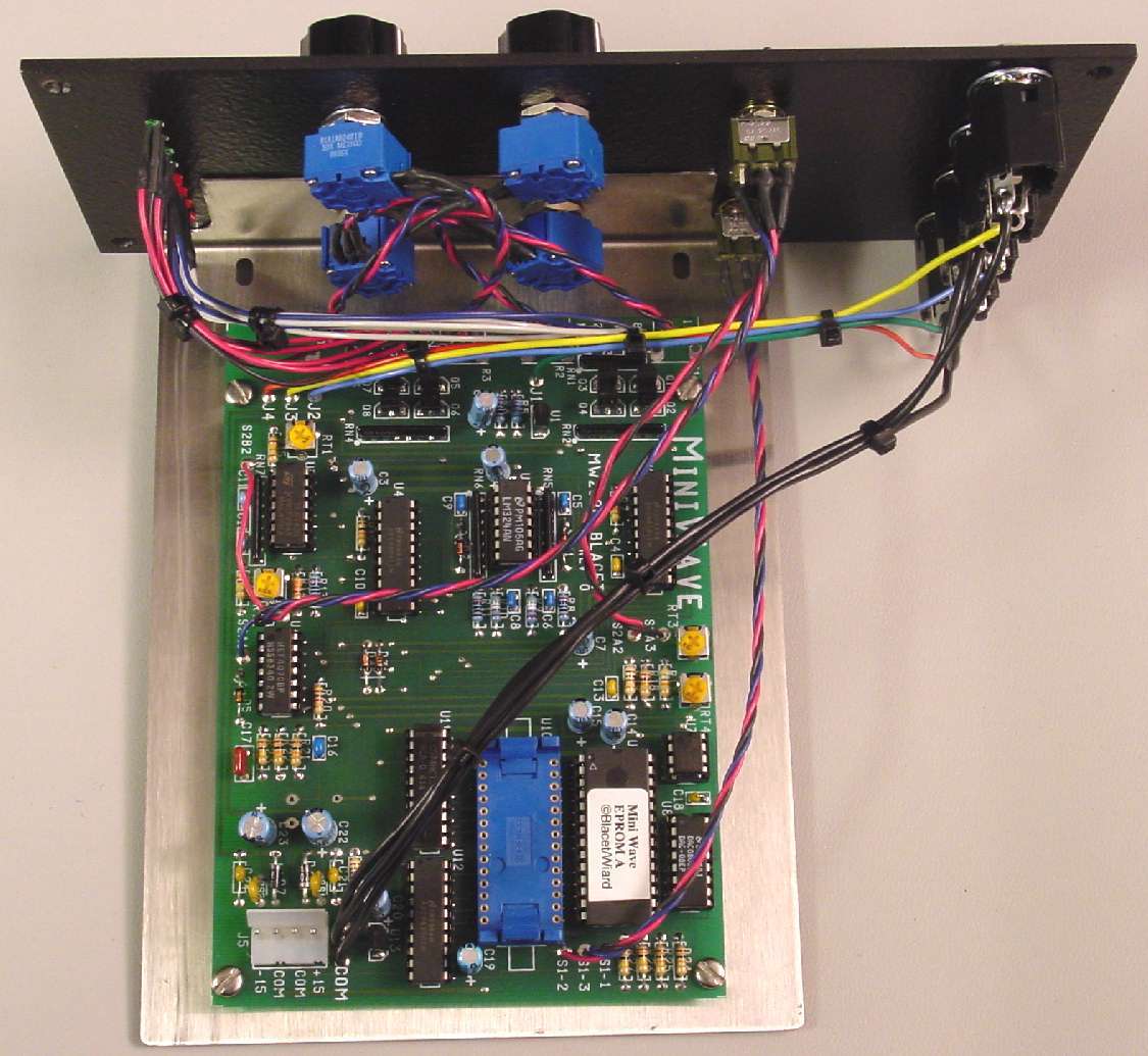
Pots and switches now attached. Ready for panel
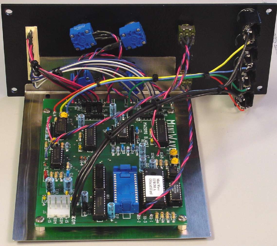
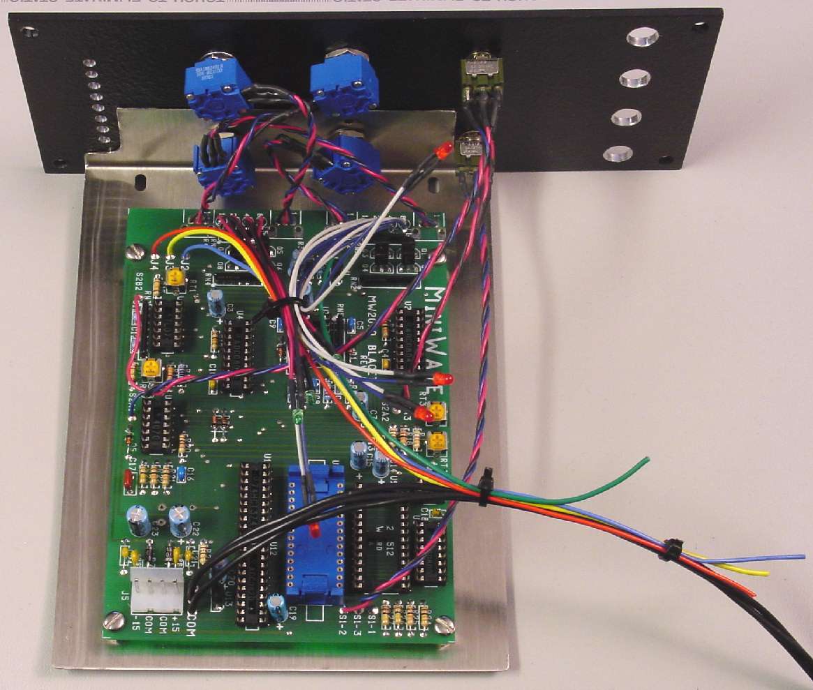
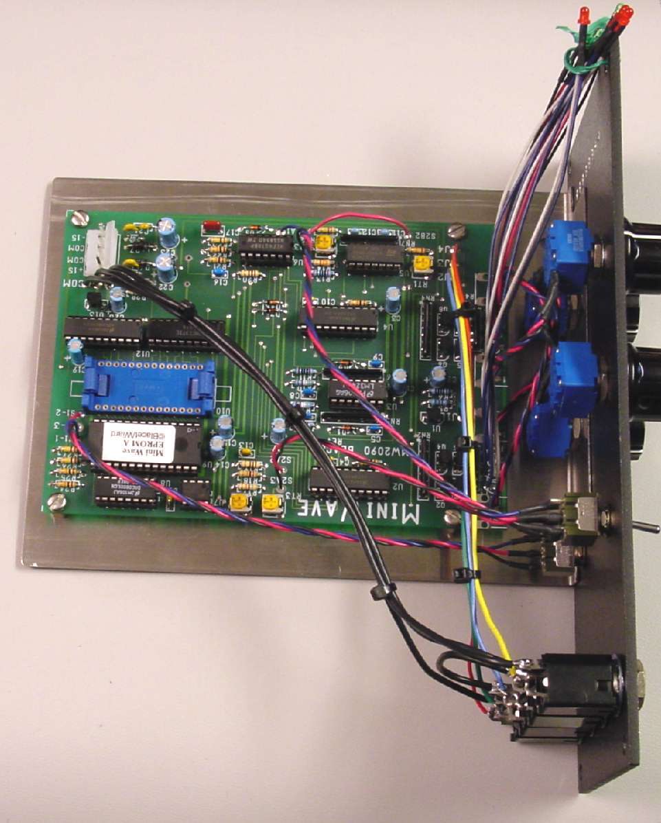
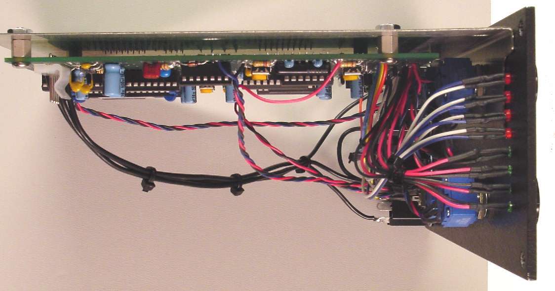
The completed Miniwave module from the rear. While the MOTM conversion does require a lot of PCB to front panel wiring, it can be kept quite neat if one takes time to twist wires together during assembly and using wire ties here and there
PCB on bracket with room up front for pots
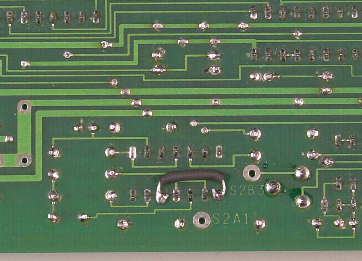
Jumper required for Rev O boards per Blacet.
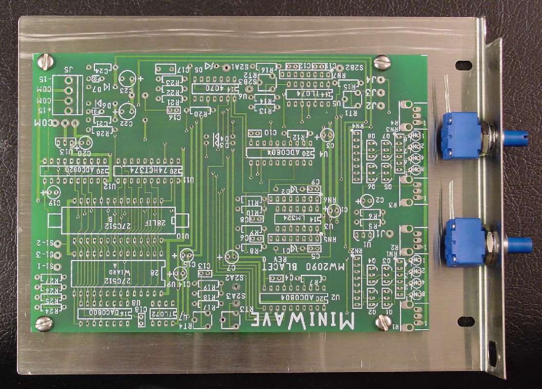
Attach to panel with pots
Trial fit bracket to front panel with pots. Looks like I need to trim around switch location too.
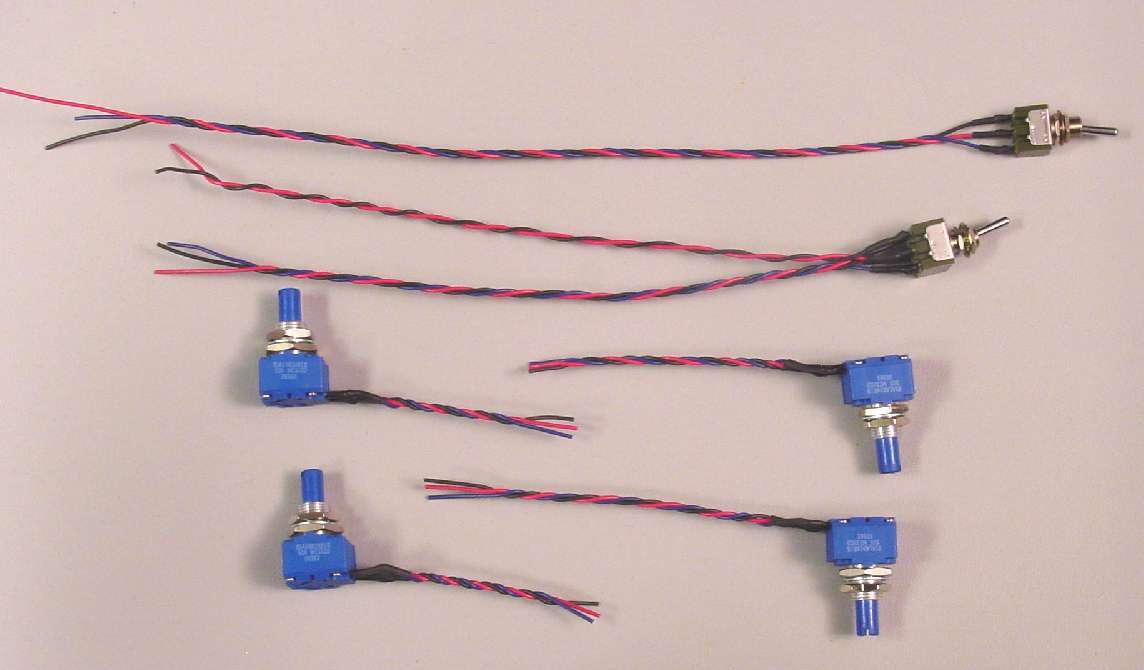
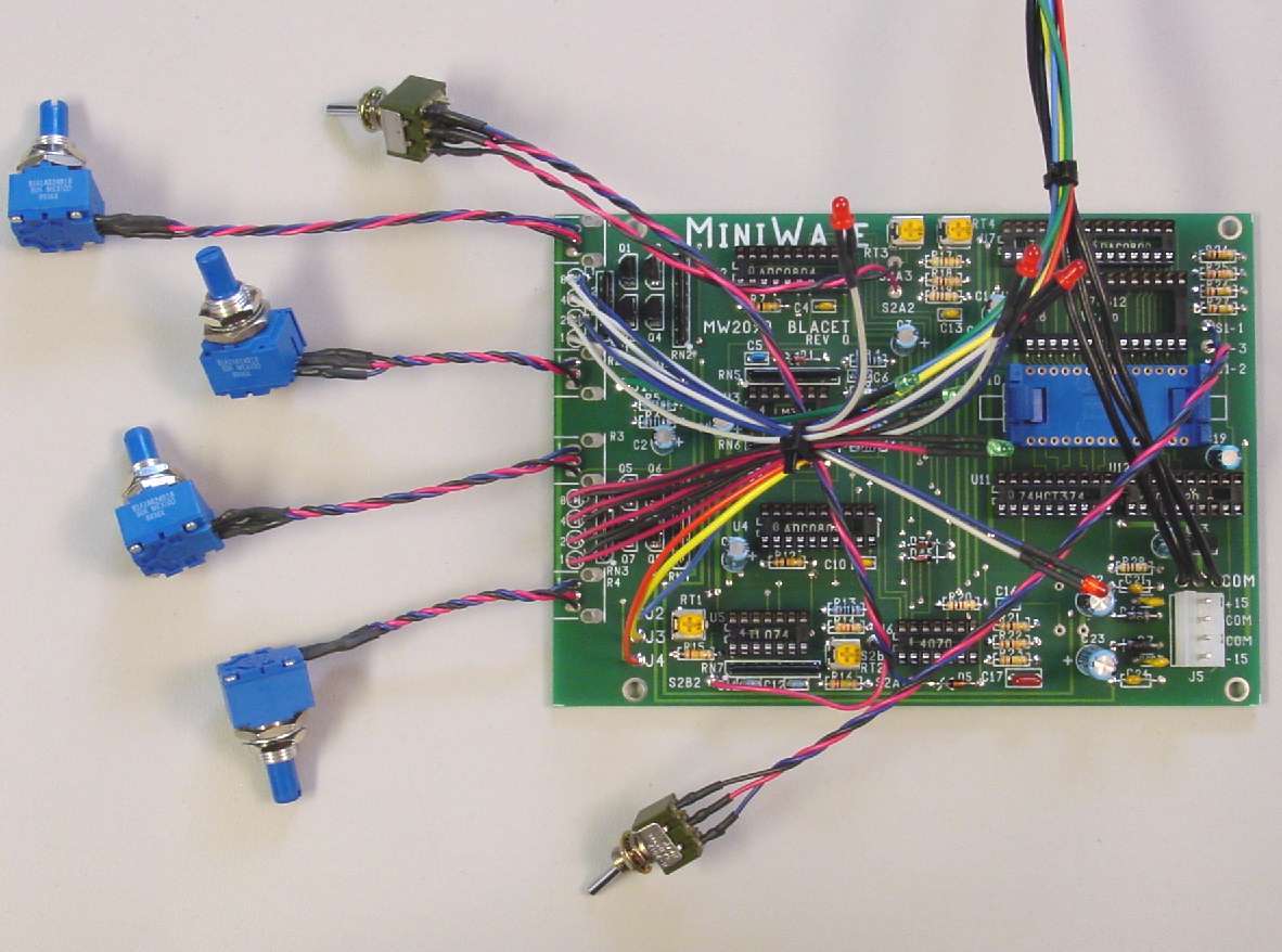
Front panel pots and switches prepared with wires to be attached to PCB. Color coded 1, 2, 3 so I do not make mistakes
Mount switches. Wire jacks
Looking at trial fit from back. Notice both end pot holes trimmed out. One for LEDs and the other for switch clearance
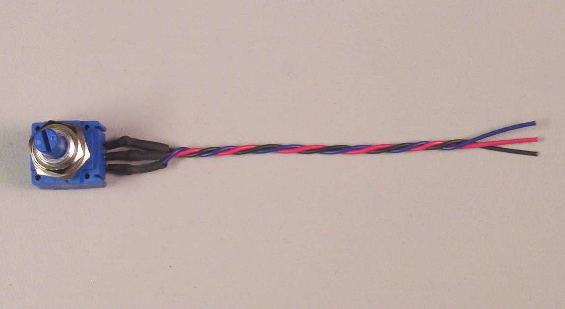
Close up of the pot with leads attached and heat shrink covering
LEDs fitted into their holes
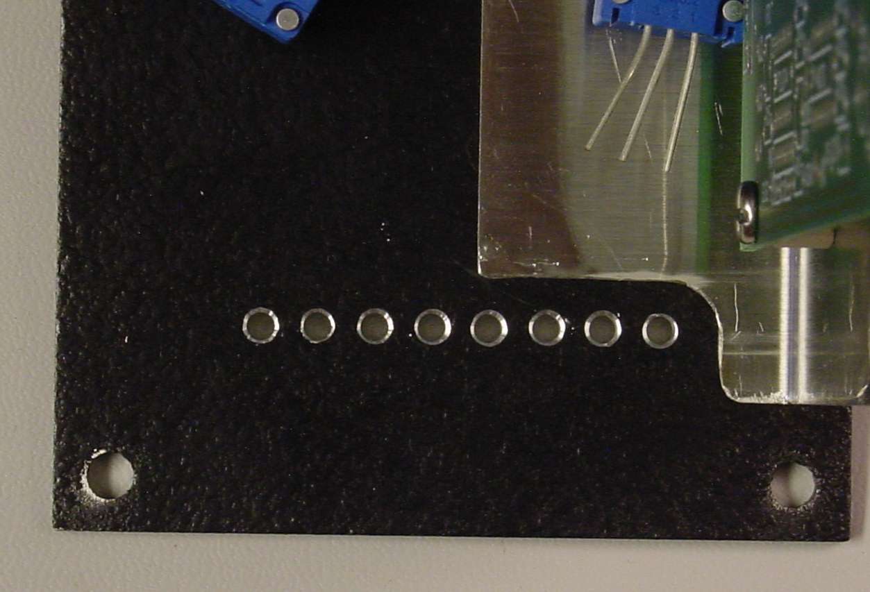
A close up of the trimming for the LED holes. Cut the pot hole straight to both edges to get this.
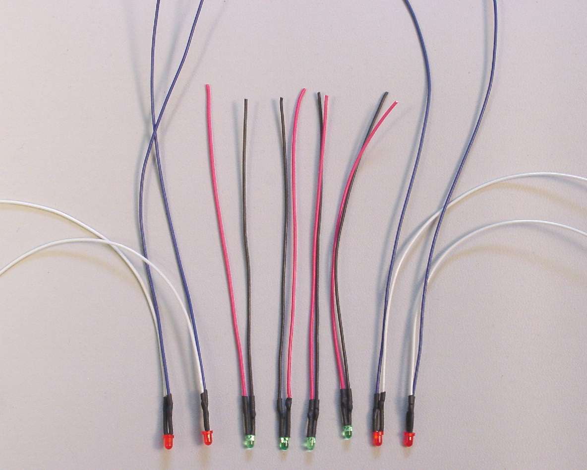
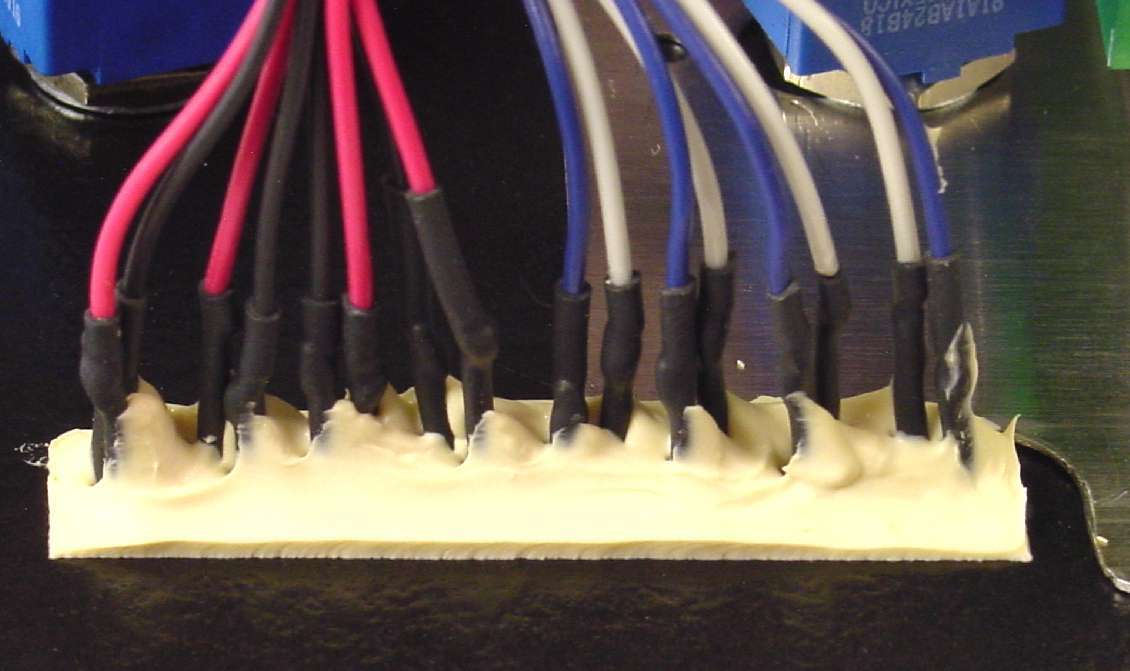
LEDs with leads attached and heat shrink applied
Top view of LEDs in their holes. They are not secured in the holes yet.
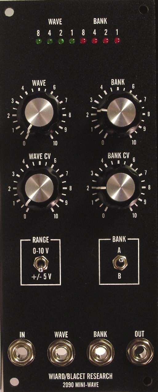
Here is the front panel view of my completed Miniwave It really looks great behind the Stooge panel and fits right into the MOTM line up. Plus the ergonomics of the layout is much better than the original Blacet panel design.
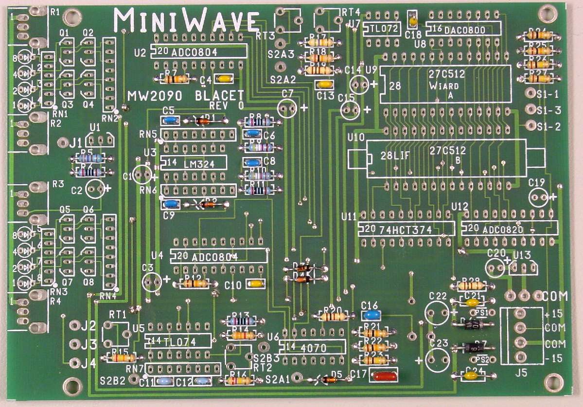
The PCB as it should appear after completing step 1 of assembly
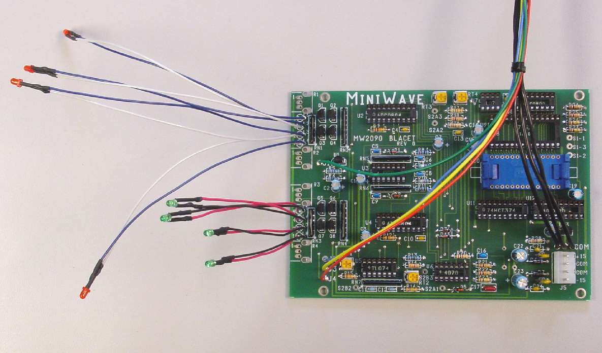
PCB with LEDs attached and leads that will attach to front panel jacks
LEDs are secured into their holes with caulk. It can be easily removed if needed