MOTM-300 VCO modification:
There are two things about the great MOTM-300 that I wanted a little different.
First was "at least" octave switches. That problem was solved and made better for many of us with the DIY 822 and 831 voltage switcher projects. Now we have instant interval and octave switching and even transpose on the fly.
Second was the fine tune control range. The fine tuning has never been "fine" enough for my personal taste. I have always felt the range of the fine tune control was greater than what I liked. The fine tune control seems too touchy when trying to zero beat oscillators to me. So, I have modified one of my VCOs (and will soon do the other four) so that the fine tune control is more fine.
On my stock MOTM 300s, the range of the fine tune control is about 11 semitones. I wanted something in the 2 to 3 semitone range on that control. The modification is simple and virtually non-destructive. It requires adding one 270K resistor to the circuit board and cutting one trace. Since the trace resides between two via holes, the modification is easily reversible by removing the resistor and inserting a wire jumper.
You can size the resistor so that the range of the fine tune control suits your own needs. If you go much above 390K, the fine control will have too little effect and be useless. 270K produced the results of 2 to 3 semitones I was looking for. Something around 100K would produce between 5 and 6 semitones. The smaller the resistor, the less reduction from the current range of around 11 semitones.
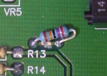
Here is the photo of my modification. The changes are very simple:
1. Locate the two via holes adjacent to R13 (near the top of the board and the fine tune pot)
2. Suck out the solder from these two via holes if you soldered them during construction.
3. Cut the trace on component side of the board between these two via holes.
4. Add your resistor by putting the leads through the via holes and soldering in place (from the bottom)
Remember to use "no-clean" solder since there will be no board washing.
This modification is easily reversible by removing the resistor and soldering a scrap resistor lead across the cut trace between the two via holes in the same way the resistor was soldered in place.
Drop me a note if you have any questions.
Click
here for print friendly PDF file.