
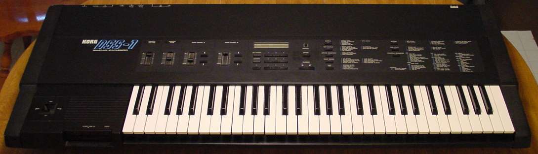
DSS-1 drive installation
When you receive your new DSS-1 disk drive from
Route 66 Studios, you willA lot of photos are included. So, please be patient waiting for your download.
Here’s what to expect in your package – The drive and one instruction page:
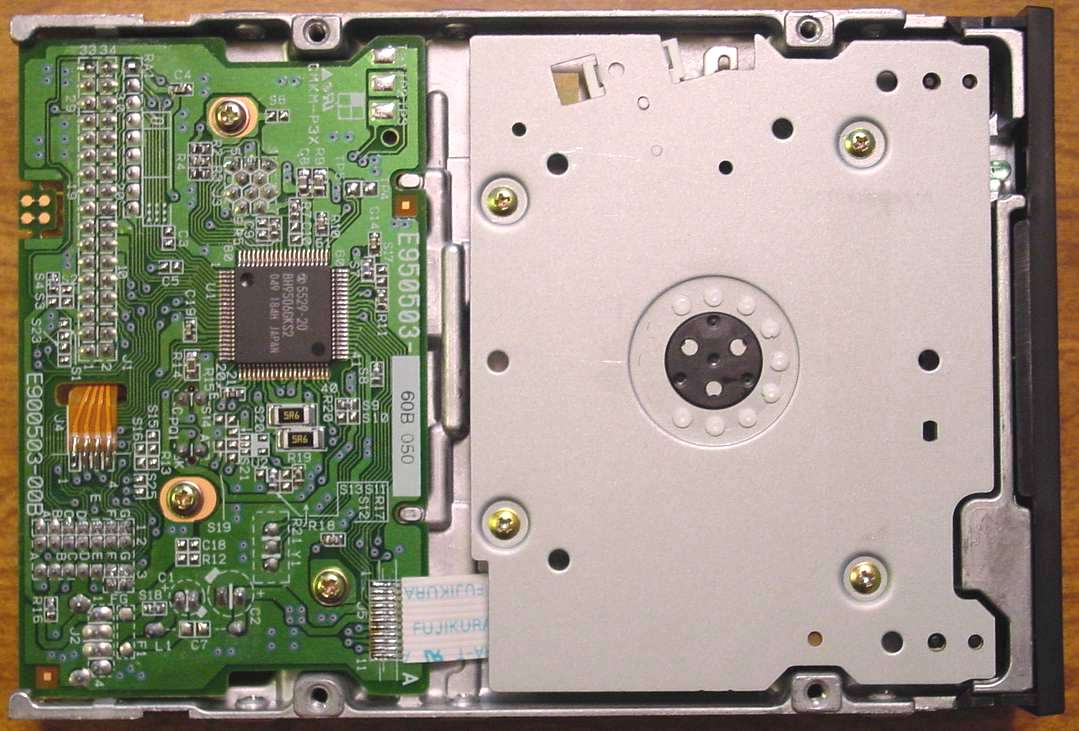
Here are some photos of the drive from the top, bottom, and front:
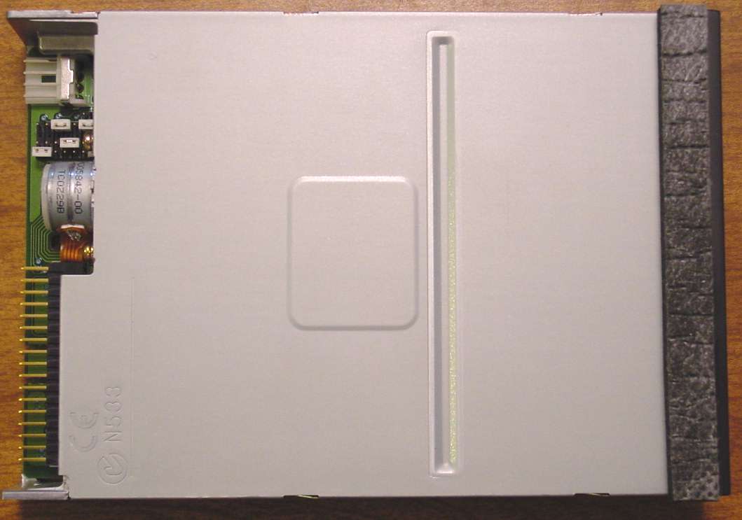
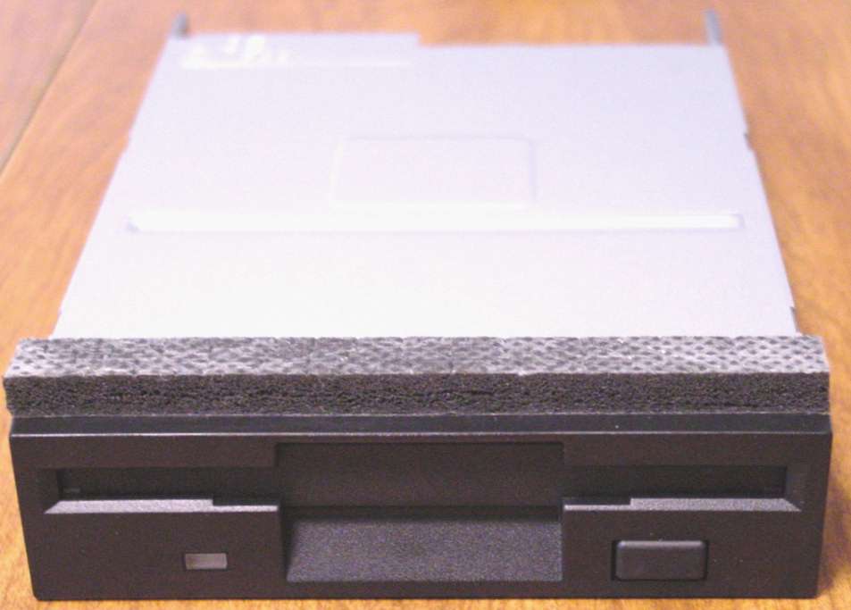
You will notice the drive has a black foam like strip across the top. Do not remove
this strip. It has been installed for a specific purpose which will become apparent
when you complete your installation.
To start your installation, you need a large work area. I found working on top of a
workbench or table was best where I could hang one end of the DSS-1 over the
edge to get at screws on the bottom side.
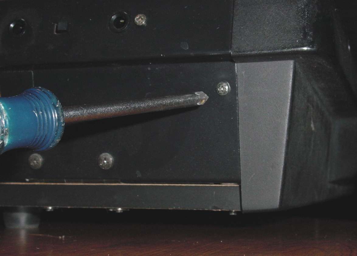
The first task is to remove 4 screws (2 on each end cap). These are medium size
Phillips-head screws. Some care needs to be exercised to line the screwdriver up
with the head and not strip out the top of the screw. You may also find that once you
have the screws fully backed out that you may need to tip the DSS-1 up from one
end to get the screws to fall out of their recessed holes.
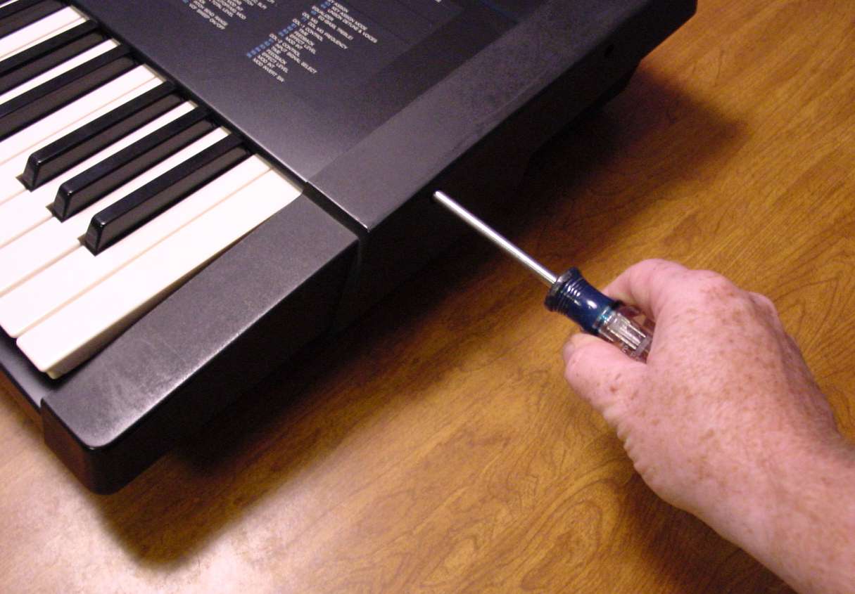
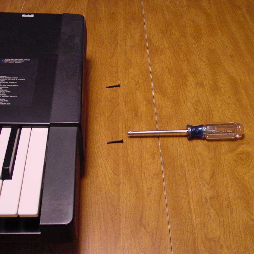
These photos show the right side, but the left side is the same.
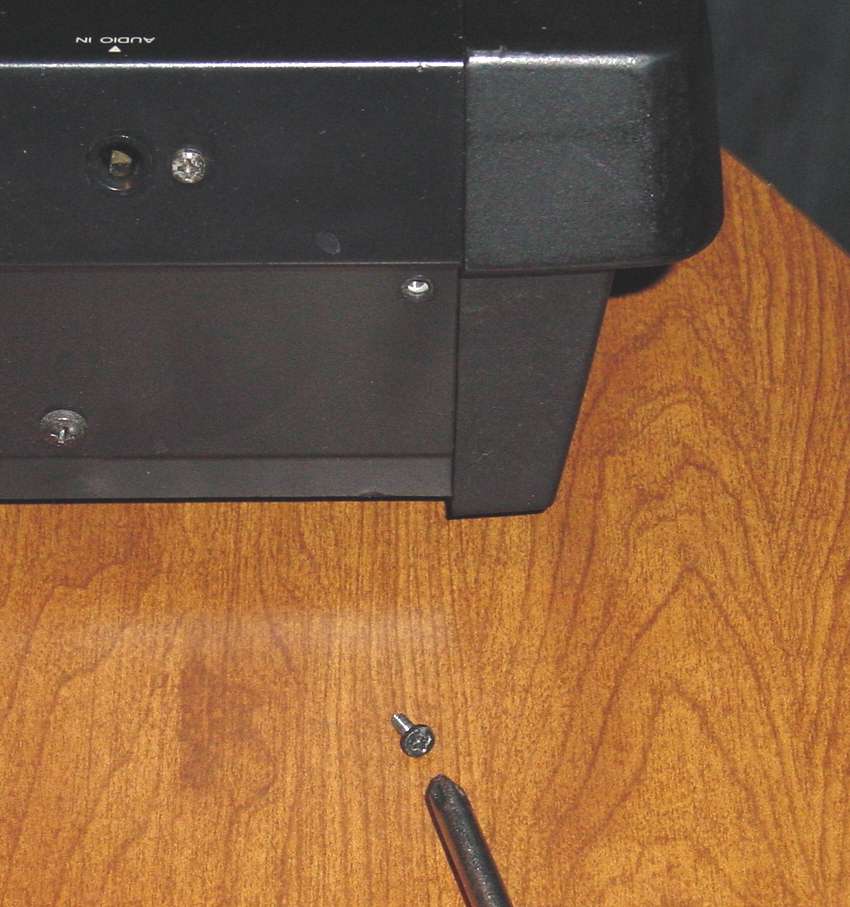
After those 4 long screws are removed, two additional screws need to be removed
on the back of the DSS-1 before the top will swing open. One is on the right, by the
AC connector and power switch.
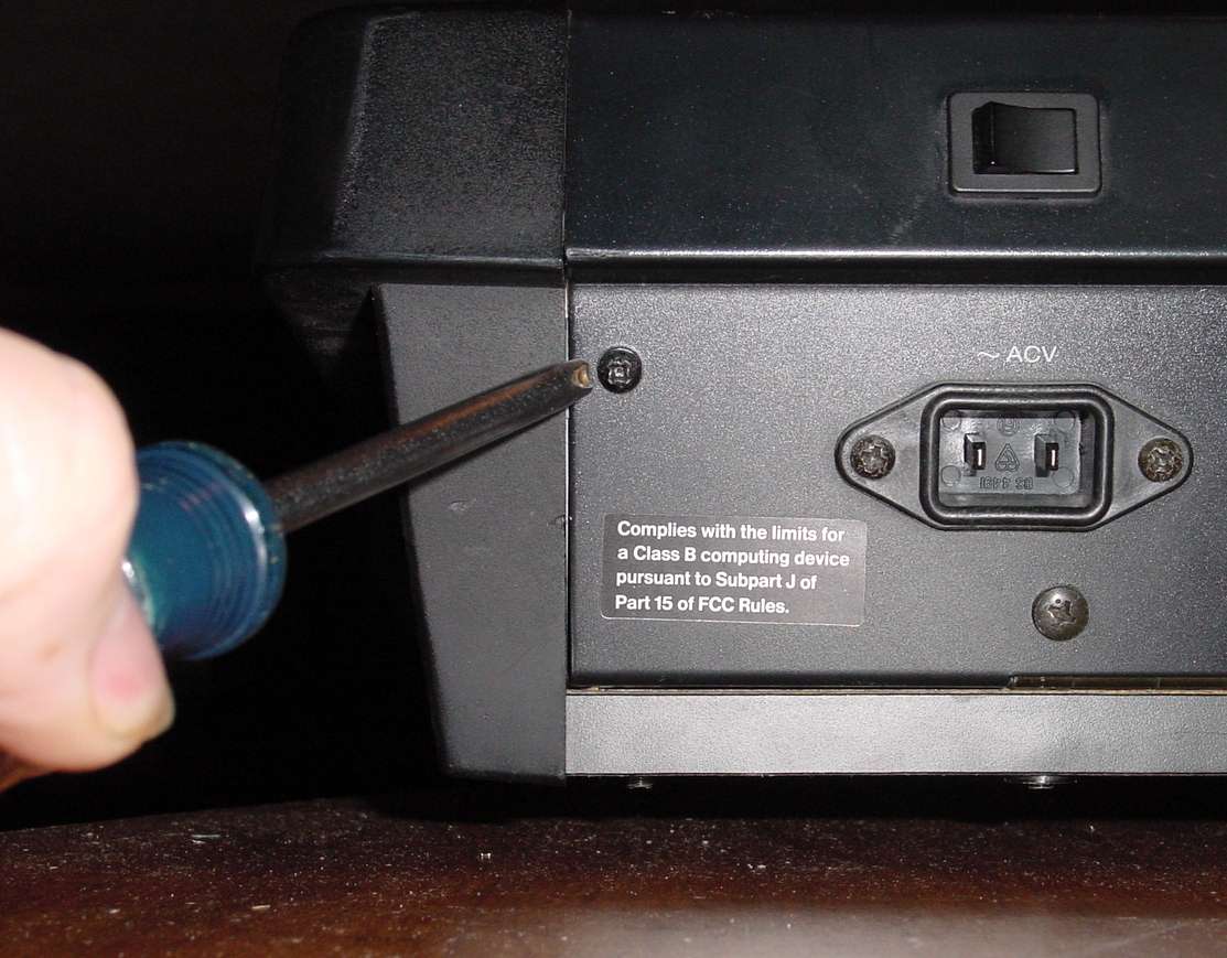
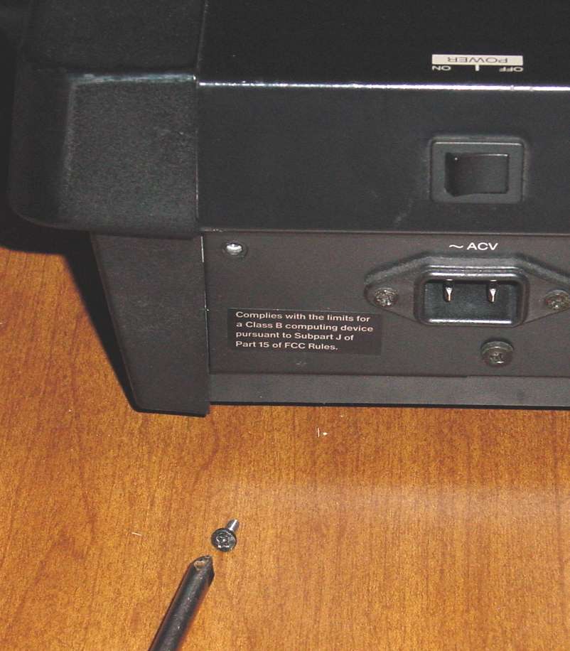
Another screw is located on the opposite side in the same location.
You will now find that the lid of the DSS-1 will easily hinge open to the back.
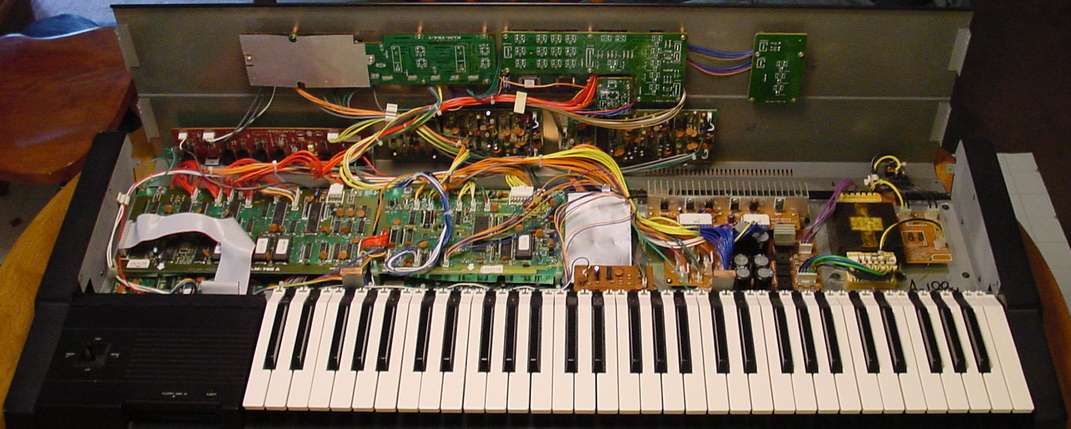
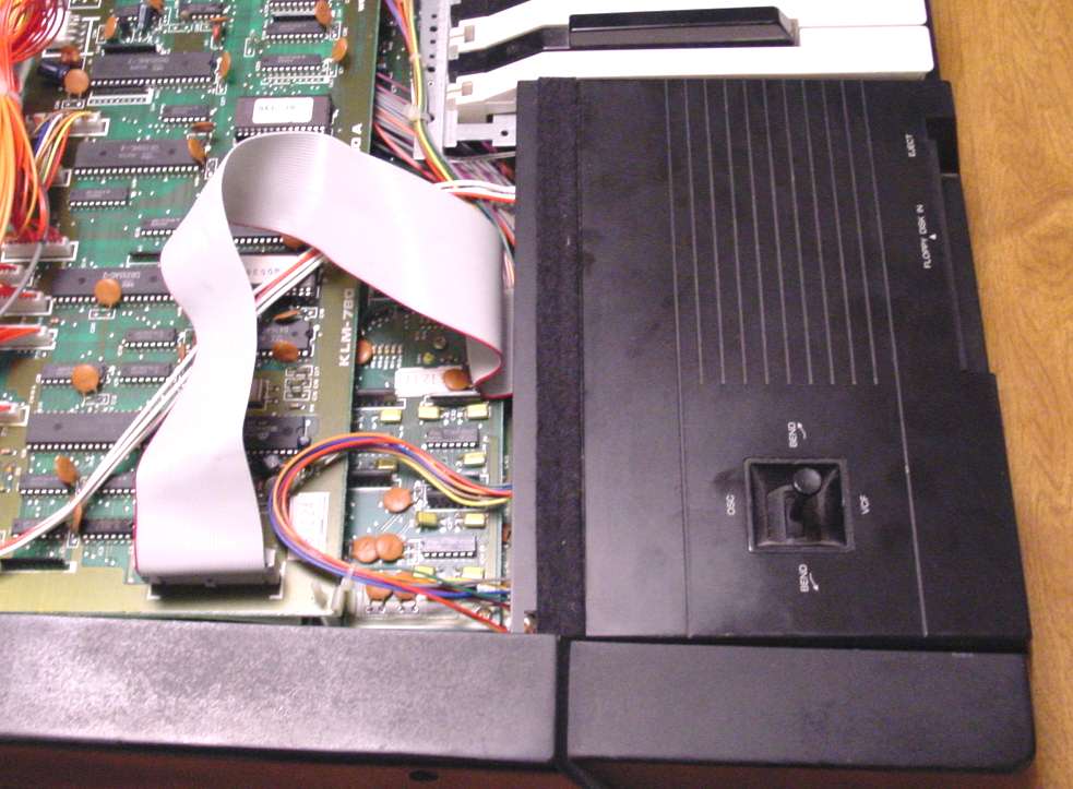
The connections to the disk drive are on the left side, behind the disk drive.
For now, close the lid so that you can remove the needed screws from the bottom
without fear of the top lid accidentally fall closed. You may find that you need to
slightly spread the end caps when you close the lid to prevent the side edges on
the lid from catching the inside metal behind the plastic end cap.
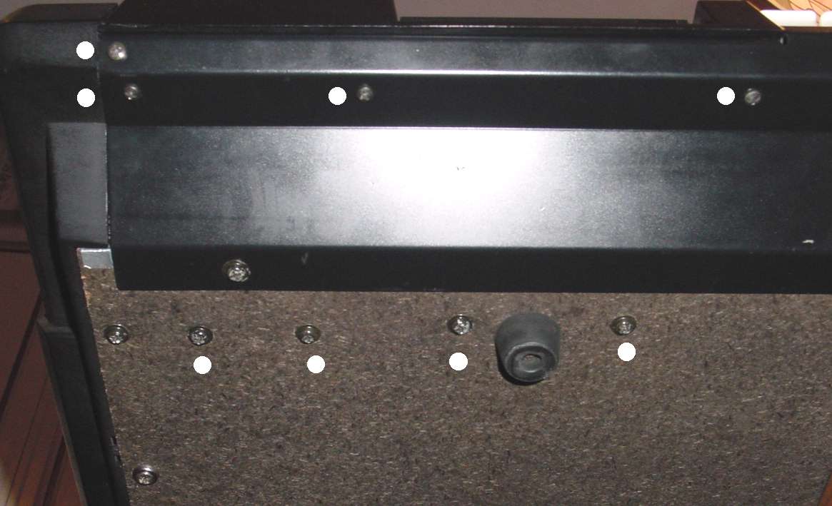
Next you will remove 8 screws from the bottom of the DSS-1, all under the area of
the DSS-1 disk drive. I positioned my DSS-1 with the disk drive area overhanging
the edge of the table so I could easily get to the screws on the bottom. I have placed
a white dot next to the 8 screws that you will be removing. Notice that the not all of the
small screws are the same. Take note so you can return them to the correct position.
Once these 8 screws are removed and the lid is hinged back open, the disk drive
bay will be completely free of the main chassis and can be easily removed.
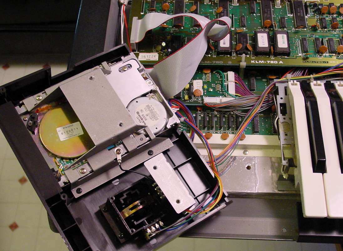
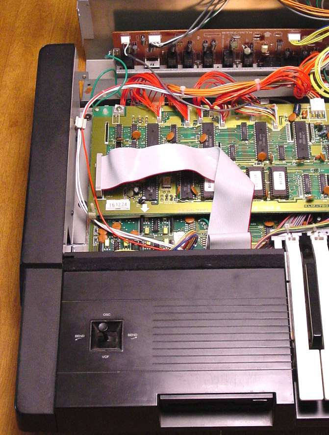
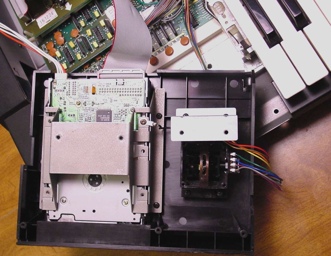
Take particular notice of the connection of the ribbon cable. The position of the
cable on the back of the new drive is slightly different, so we want to be sure we
hook it back up correctly. Disconnect the power cable and ribbon cable. Then,
the drive assembly can be removed from the DSS-1 chassis, but will remain
connected by the wiring to the Joystick.
Once the drive assembly is removed, you are ready to remove the disk drive from this
assembly. Care must be taken not to damage the Joystick controller protruding from
the top of this assembly. I positioned my drive assembly so that the joystick portion
overhung the edge of the table prior to starting the drive removal. There are 4 small
screws that hold the drive into the assembly.
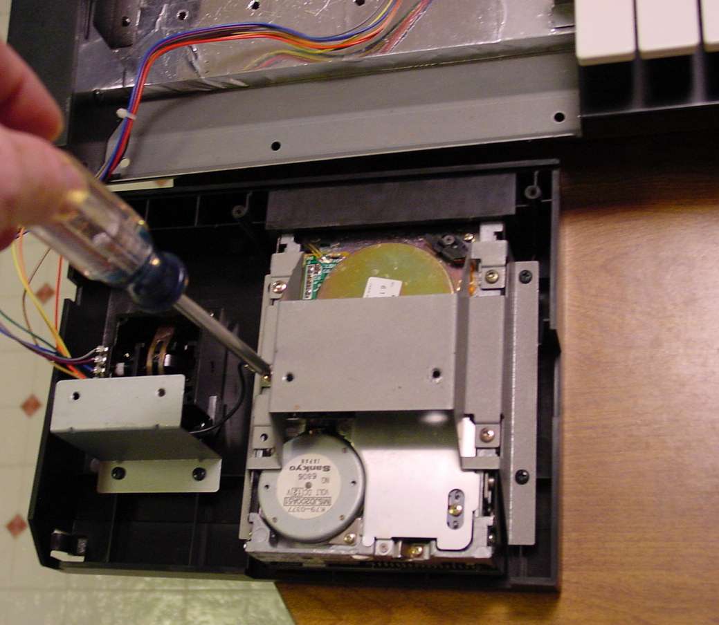
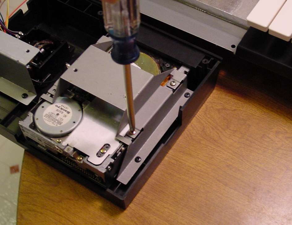
Once these 4 screws are removed, the disc drive will easily slip right out from the front.
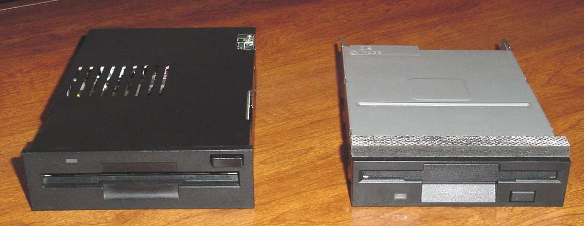
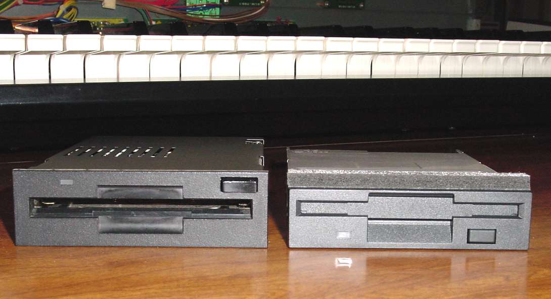
After you have the drive removed, take an opportunity to notice the physical differences
between the original DSS-1 drive and the replacement. You will see the replacement
drive is not as tall as the original drive. Here are some photos from the top, front, and
side.
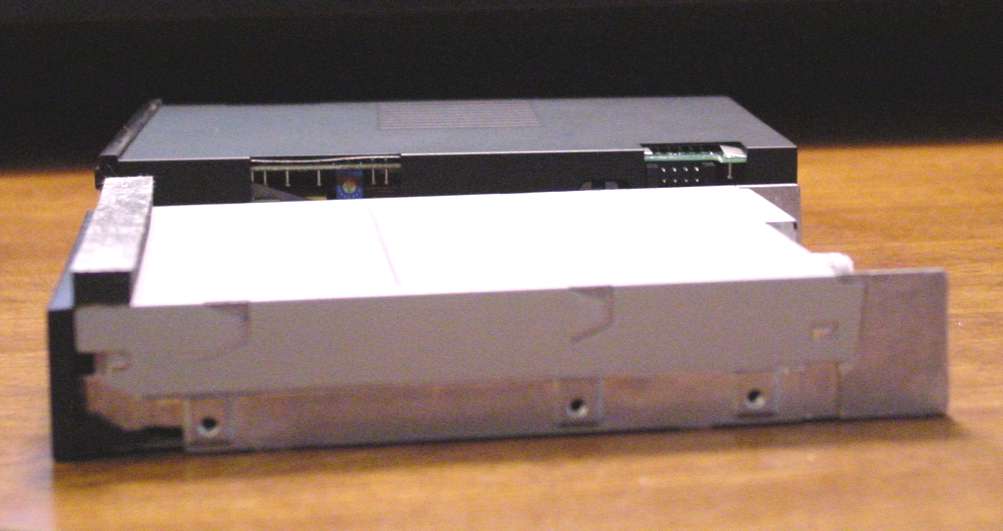
Now you can easily see the purpose of the foam strip across the top of the drive.
This strip fills in the gap because of the difference in height of the two drives. This
keeps foreign particles from entering your DSS-1 and makes the appearance much
more like the drive was original equipment. Kudos to Richard for including this extra
touch to dress out the appearance of the replacement drive installation.
Now, lets examine the connections to the back of the new drive. The power connection
is easy. It will only fit on in one direction. Properly installed, it will snap and slightly lock
into position. The ribbon cable is a different case. When plugging the ribbon cable, do
not use excessive force or pins can easily be bent over. Be sure all pins are aligned
with the connector before pushing the connector on. What about polarity? Notice in the
first photo. I show the ribbon connected with the red wire toward the power connector
on the drive. In this case, the connector to the main circuit board remains connected as
it was before.
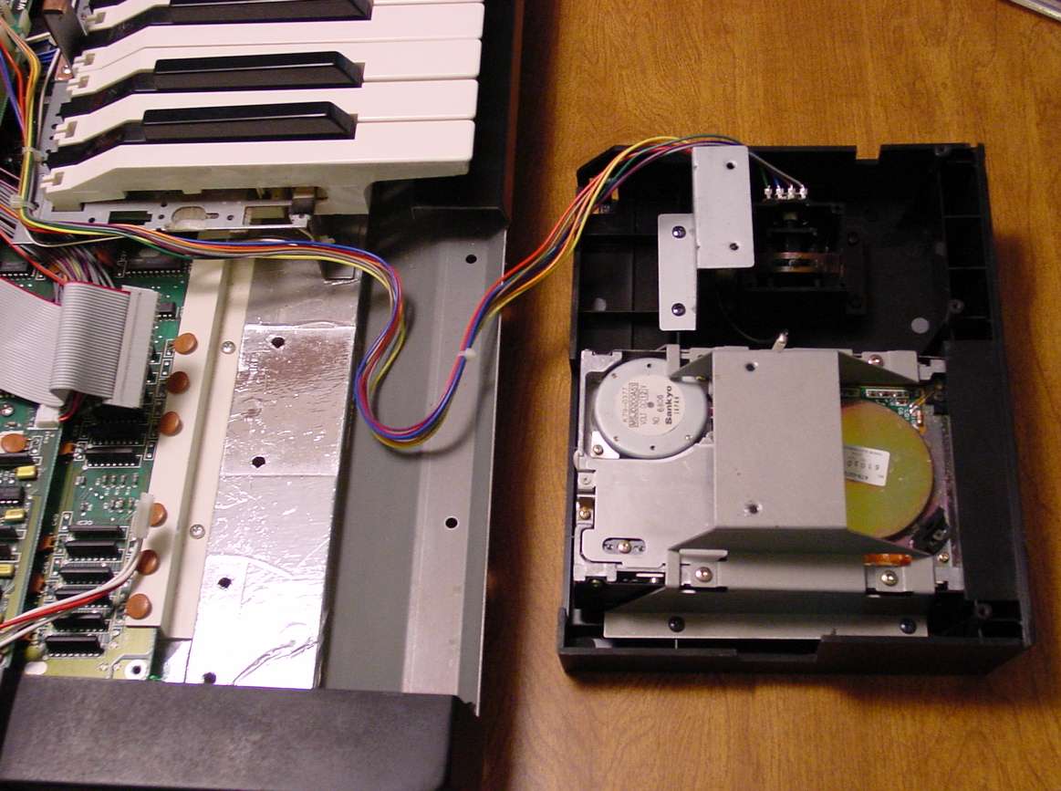
Notice in this second photo that shows the drive assembly reinstalled, the red wire
on the ribbon cable is positioned away from the power connector. You may find that
connection necessary due to mechanical interlocking on the new disk drive. If so, you
will also need to reverse the connection on the PCB. Notice that normally, the red
wire on the ribbon cable was toward the front of the DSS-1. But, in this configuration,
the red wire is toward the back. Once you have the cable connected to your drive, you
can decide which connection is appropriate on the board.
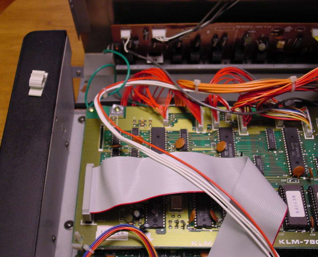
One more issue is the length of the disk drive power cable. The connector on the replacement drive is on the opposite side from the original. I found it necessary to
remove the plastic cable clamp on this inside of the DSS-1 end cap to provide the
additional length needed for the power cable.
At this point, you can close the lid on your DSS-1 and give your new disk drive a trial run
before replacing all the screws. Assuming all works OK, first replace all 8 screws on
the bottom. As you insert each screw, do not tighten it completely until you have all 8
screws started. That will assist you in aligning all screws. Then, tighten all screws.
With the lid closed, replace the 2 screws on the back of your DSS-1. Then, insert all
four of the long screws in the end caps to prepare for tightening. You will find that
starting these screws requires you to pull the lid into alignment so the screws line up
with their threaded holes. Start all 4 screws before tightening the any of them. Do not
over-tighten these screws. You installed drive should look like this.
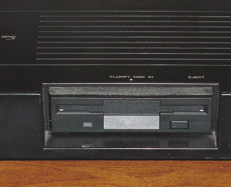
Congratulations! You have completed your DSS-1 disk drive replacement and your
DSS-1 has now returned to full function. Neither of my DSS-1 disk drives has actually
failed. However, I ordered a spare for each. I could not bear to lose either of my DSS-1
synths to drive failure.